Alex_bam
New Member
Hello,
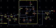
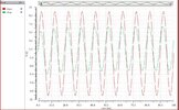
Could anyone review my 2nd order Butterworth HPF design? I have mentioned design details along with schematics and initial results.
Design specifications for 2nd HPF: Cutoff frequency= 100Mhz, Design method: by considering equal component, Input signal= 10V,120MHz, sinosidal.
Design specification for OPAMP: Slew rate= 5V/usec , CL=10pF, ICMR+= 4.5V, ICMR-=1.5V , Vdd=5V, GBW>=5MHz, W/L ratio is mentioned with each transistor.
According to the calculations, it should work but I do not know where I am making mistakes...
Thanks