Electro Tech is an online community (with over 170,000 members) who enjoy talking about and building electronic circuits, projects and gadgets. To participate you need to register. Registration is free. Click here to register now.
Welcome to our site! Electro Tech is an online community (with over 170,000 members) who enjoy talking about and building electronic circuits, projects and gadgets. To participate you need to register. Registration is free. Click here to register now.
if we just tell you the answer straight off, you won't learn much. How about you tell us what you think the answer is, or work us through the problem until you get stuck, and we can point out where you went wrong.
Ok. For the first question (the resistors), I tried calculating Rtot. I first added the 55R and 22R resistors (cause they're in series). Then I added the 10R and 22R. Then I used the R parralel equation: 1/Rt = 1/R1 + 1/R2 + ... I substituted in: 1/Rt = 1/22 + 1/78 + 1/22. My final answer was 9.64R. Then to calculate It, I said: IT = Vt/Rt. 1/9.6 and I got 0.103A. Then I tried to calculate the Pd accross the R22 resistor: V= IR: (0.102)(22). This gave me 1.14V? Is this correct?
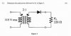
Then the second question (transformer peak) I said Vin = 115V rms, so I thought that the Vout will be 115/2 because the ratio is 2:1. I then got 57.6V. But where do I go from there? Can I use the Vavg = Vp(out)/pi to calculate the voltage?
The first question is a short because the batteries + is connected to ground :lol:, probabely a printing error
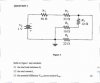
you need to add the 10 and 12 ohm resistor because they're in series, then the resulting resistor is in parallel with the lower 22 ohm resistor, so you need to calculate their result.
then finally, add the 56 ohm and the upper 22 ohm, the result of this is in parallel with the previous result. you can calculate total resistance from this.
for the second question, you know the voltage, and you know the load resistance. You can calculate the current from this (ohm's law)
when you know current and voltage you can calculate power
R1 and R2 are series-connected with the parallel net made up of the R3/R5 series pair and R4. The effective value of the R3/R5 pair is the same as the value of r4, making the effective value of the parallel net 1/2 of the value of either leg, or in this case 11 ohms. This is taken in series with the R1 and R2 for the total circuit resistance, giving 89 ohms (56 +22 + 11).
OK -- that means that the circuit current will be 1 volt divided by 89 ohms, or 11.236mA. Assuming resistor values to be exactly as labeled (IOW a perfect world... ), that current will flow through the R1/R2 series pair, and will then be evenly divided through the parallel net -- with 5.618mA through each leg.
The question itself is poorly worded, as it asks for voltage drop across the 22 ohm resistor, but it doesn't specify which 22 ohm resistor to consider. If considering R2, the answer would be 22 ohms x 0.011236A = 0.247192 volts. However, if If considering R4, we have to look a little bit deeper. The parallel net of R3/R4/R5 will drop 0.123596 volts of the original (source) 1 volt -- 0.011236A x 11 ohms. We could use this value to calcualate individual drops within the parallel net, but more importantly, this would also then be the voltage across R4. This can be verified by going back to the parallel leg current figured above... 22 ohms x 0.005618A = 0.123596 volts.
Some further voltage drop analysis...
R1 will drop 0.629216 volts (0.011236A x 56 ohms)
R2 will drop 0.247192 volts (already discussed)
The R3/R4/R5 parallel net will drop 0.123596 volts (0.011236A x 11 ohms)
R3 will drop 0.05618 volts (0.005618A x 10 ohms)
R4 will drop 0.123596 volts (already discussed)
R5 will drop 0.067416 volts (0.005618A x 12 ohms)
Not that the total voltage dropped by R3 and R5 is equal to that dropped by R4, which makes sense because they are parallel branches. Note too that the raw sum of all voltage drops given above is greater than the source voltage. This is normal and is to be expected because of the fact that there are parallel branches involved. The sum of the drops across R1 + R2 + the R3/R4/R5 parallel net should equal the source voltage, with a slight error for rounding.
Finally, I sincerely hope that the comments regarding the question being a trick question and/or the circuit having a short (because of the positive grounding) were in jest. The is no rule stating that the negative side of the source MUST be grounded... indeed, for many years, cars and trucks used positive grounding, as just one example.
This site uses cookies to help personalise content, tailor your experience and to keep you logged in if you register.
By continuing to use this site, you are consenting to our use of cookies.

")