https://www.mpja.com/LCD-Display-240-X-128-Graphic-with-Backlight/productinfo/31003+OP/
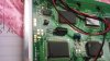
I just purchased this LCD display and was wondering what the extra red/black wire is for. You can download the datasheet from the above link. I'm also wondering what the data sheet means by "# Has built-in inverter for negative power supply" on page 23.
I just purchased this LCD display and was wondering what the extra red/black wire is for. You can download the datasheet from the above link. I'm also wondering what the data sheet means by "# Has built-in inverter for negative power supply" on page 23.