Electro Tech is an online community (with over 170,000 members) who enjoy talking about and building electronic circuits, projects and gadgets. To participate you need to register. Registration is free. Click here to register now.
Welcome to our site! Electro Tech is an online community (with over 170,000 members) who enjoy talking about and building electronic circuits, projects and gadgets. To participate you need to register. Registration is free. Click here to register now.
from my stand point as a newbie i believe it's pointless since the same job can be done with a single transistor which uses much less space...
but i don't know if it is more stable than a transistor oscillator...
probably not because in case you aproach the antenna you'll add
directly to the oscillator and the frequency will change.
probably it's nice for show off...so you can prove that you can manipulate
component properties and you give new functionalities..
atleast it oscillates right?
-------------------------------------------
probably it's nice for show off...so you can prove that you can manipulate
component properties and you give new functionalities..
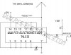
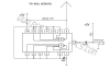
Aside from that, pin usage on the chip appear to be all wrong. Mic inputs to nand gate but output of gate is tied to some quasi funky common of all pins. Circuit is just, well not right.
I do not see how this thing could have worked at all.
Aside from that, pin usage on the chip appear to be all wrong. Mic inputs to nand gate but output of gate is tied to some quasi funky common of all pins. Circuit is just, well not right.
I do not see how this thing could have worked at all.
I find the circuit to be absurd. or to put it in other terms; It is crap, garbage, junk, spew, rubbish, nonsensical, silly, painfully unthoughtful, and lacking insight. In other words, the circuit is garbage and I fail to understand why it was not disposed of while the dumpster truck approached it's vicinity.
Perhaps you should build that futile circuit, just so you learn, not all web sites post decent material.
It looks like it will oscillate but I can't see it having an FM. I don't know may be the Schmitt trigger thresholds might change if the voltage on a neighbouring input is varied?
It certainly is a rubbish circuit and will produce lots of harmonics.
This site uses cookies to help personalise content, tailor your experience and to keep you logged in if you register.
By continuing to use this site, you are consenting to our use of cookies.