Continue to Site

Welcome to our site!

Electro Tech is an online community (with over 170,000 members) who enjoy talking about and building electronic circuits, projects and gadgets. To participate you need to register. Registration is free. Click here to register now.

  • Welcome to our site! Electro Tech is an online community (with over 170,000 members) who enjoy talking about and building electronic circuits, projects and gadgets. To participate you need to register. Registration is free. Click here to register now.

Wiring a single phase motor ,forward ,reverse

Status
Not open for further replies.

Gregory

Member
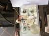
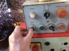
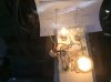
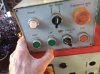
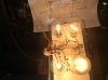
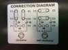
I have to replace a new motor on my milling machine.Single phase cap run cap start. Forward and reverse.
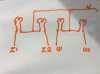
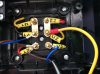
There is 4 wires 2 red 2 black.
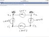
How do I connect the wires into the motor with cap run cap start for forward and reverse.
 

Attachments

  • C202AC0A-81AE-4C7E-8A8B-1A944799D235.jpeg
    C202AC0A-81AE-4C7E-8A8B-1A944799D235.jpeg
    1.2 MB · Views: 11,106
  • 44D2E4F1-C73B-456C-81C2-2500C01F9AC8.jpeg
    44D2E4F1-C73B-456C-81C2-2500C01F9AC8.jpeg
    1.1 MB · Views: 7,406
  • F35470F8-BB7B-4BE3-BE86-C93A0FA1F82C.jpeg
    F35470F8-BB7B-4BE3-BE86-C93A0FA1F82C.jpeg
    731 KB · Views: 1,308
  • 9A76D468-8410-4A72-8CC2-A50224540F30.jpeg
    9A76D468-8410-4A72-8CC2-A50224540F30.jpeg
    709 KB · Views: 1,537
  • 413EB005-32D9-49BD-B90F-B675E2A96462.jpeg
    413EB005-32D9-49BD-B90F-B675E2A96462.jpeg
    989.4 KB · Views: 522
  • 45C1E483-561A-42AE-B12D-23DE7C058CDD.jpeg
    45C1E483-561A-42AE-B12D-23DE7C058CDD.jpeg
    1.2 MB · Views: 720
I don't think the way you have labled the wires as live and neutral is correct. I think red is one winding and black is the other winding. If I am right then on the old motor you should measure a low tesistance (Less than 20 ohms.) between the teminals that had the red wire connected to them. You should also measure a low resistance between the teminals that had the black wires connected to them. There should be a very high resistance (Greater than 50 Meg ohms.) between a terminal that had a red wire and a terminal that had a black wire. If you get these reading then the following instructions should do what you want.
Remove the two metal straps but put the wires back on the same terminals. Connect the wire labled U1 to terminal U1. Connect the wire labled U2 to terminal V2. Connect the wire labeled Z1 to terminal V1. Connect the wire marked Z2 to terminal Z2. I assume FR is a thermal cutout switch. This will now only disconnect the main winding. To use it to disconnect both windings you would need to run two more wires back to the control box and connect it in series with the live feed to the forward and reverse contactors. There may already be thermal overcurrent protection in the control gear. If you post a schematic we should be able to see if this is the case. If forward and reverse are the wrong way round swap over the wires U1 and U2.

Les.
 
Last edited:
I do not have the motor as it was burnt out .
Would you like me to trace each wires back From the motor connection to the contractors and draw them up.
 
Last edited:
Hi Gregory,
That would be one way but it may be quicker to connect the four wires to four lamps (Old filiment type bulbs. The wattage is not important. ) Connect them like this.


Z1 ------(Lamp 1)-------Z2
|..................................... |
|......................................|
(Lamp 3)...................... (Lamp 4)
|......................................|
|......................................|
U1------(Lamp 2--------U2
In one direction all four lamps will light. In the other direction only two lamps will light. The lamps that light in both directions are the ones connected between the wires for a winding. If it is wired how I think it is then lamps 1 and 2 will be lit in both directions. If this is the case then the way I suggesred connecting the motor should be correct. Post the results. The UK time of this post is about 09:11 so you have an idea of the time difference.
Edit. I had to add the ....s as the forum software removed the spaces so the diagram did not make sense.

Les.
 
Last edited:
Is this the way you want the. bulbes to be wired up .
 

Attachments

  • DC71411F-AFB8-4F10-B1B2-40505C6B70CE.jpeg
    DC71411F-AFB8-4F10-B1B2-40505C6B70CE.jpeg
    782.1 KB · Views: 214
Hi Gregory,
No, that is not the way I want them connected. I am making the assumption that the machine is fed with a single phase 240 volt supply, the motor is single phase 240 volts and the lamps you use are 240 volts. This is how I want the lamps connected.
220418.jpg

I have assumed that U1 and U1 connect to the main winding and Z1 and Z2 connect to the aux. winding. (Via the capacitors and centrifugal switch in the motor.) To reverse the motor the polarity of the supply to one winding is reversed.
So for forward we will say that U1 is connected to neutral and U2 is connected to live and Z1 is connected to neutral and Z2 connected to live.
For reverse U1 is connected to neutral and U2 is connected to live and Z2 is connected to neutral and Z1 connected to live.

For forward the lamp pins will be connected as follows.
Lamp 1 N &L (On) (Z1 = N, Z2 = L)
Lamp 2 N&L (On) (U1 = N, U2 = L)
Lamp 3 N&N (Off (Z1 = N, U1 = N)
Lamp 4 L&L (Off) (Z2 = L, U2 = L)

For reverse the lamp pins will be connected as follows.
Lamp 1 L &N (On) (Z1 = L, Z2 = N)
Lamp 2 N&L (On) (U1 = N, U2 = L)
Lamp 3 L&N (On) (Z1 = L, U1 = N)
Lamp 4 N&L (On) (Z2 = N, U2 = L)

I hope this makes it clear how this test works,
Les.
 
I have setup the light bulbes and taken pictures
Which terminals do I place the wires onto the motor.
Thank you for your help as I have learnt something.
Greg
 

Attachments

  • 4019A541-4383-45CA-9C3D-E5F7D622F1FD.png
    4019A541-4383-45CA-9C3D-E5F7D622F1FD.png
    506.2 KB · Views: 272
  • B6DA886C-C2CF-4B86-A349-0FC321424C5E.jpeg
    B6DA886C-C2CF-4B86-A349-0FC321424C5E.jpeg
    1.2 MB · Views: 181
  • E2CD8A74-A7BB-459A-BB94-693A33A0B6DC.jpeg
    E2CD8A74-A7BB-459A-BB94-693A33A0B6DC.jpeg
    1.1 MB · Views: 180
  • A7A41C2F-4C8E-4B99-BDD4-E7A1538FA603.jpeg
    A7A41C2F-4C8E-4B99-BDD4-E7A1538FA603.jpeg
    920.5 KB · Views: 199
  • FB41CFAB-E11D-40AB-AE0B-1016BCD0E596.jpeg
    FB41CFAB-E11D-40AB-AE0B-1016BCD0E596.jpeg
    1 MB · Views: 186
  • EA48BD31-706F-47DB-B9A1-69DCD6A3FF31.jpeg
    EA48BD31-706F-47DB-B9A1-69DCD6A3FF31.jpeg
    880 KB · Views: 168
Remove the two metal straps but put the wires back on the same terminals. Connect the wire labled U1 to terminal U1. Connect the wire labled U2 to terminal U2. Connect the wire labeled Z1 to terminal V1. (NOT Z1. ) Connect the wire marked Z2 to terminal Z2. If forward and reverse are the wrong way round swap over the wires U1 and U2. This is almost the same as post #2 but I now think the switch FR is the external switch / contactor controlling the motor. I originally thought it was an internal thermal cutout. It is in the wrong place to be the centrifugal switch contacts. I think the centrifugal switch is connected to terminals V1 and V2. If so then if you measure the resistance between V1 and V2 then the reading should be much less than one ohm. If the motor does not start then switch off straight away so as not to caue any damage. Let me know how you get on. By the way which time zone are you in in Australia ?

Les.
 
It is 6 30 pm here in NSW IN AESTRALIA I am on the east coast Easton time zone
New South Wales Newcastle.
Thank you.
I will try what you have written.
Greg
 
Last edited:
Thank you for your help . The motor is rotating , the Right direction is good When I start the motor in the left direction it starts but is a bit sluggish to get up to speed for a few seconds. Is this because it is starting on the run capacitor . Should I replace the capacitor with a run capacitor the same mf as the motor start cap . Would this fix the problem.
Or is there a other solution.
Greg
 
Hi Greg,
The same capacitor should be the the start capacitor in both directions. This diagram is my understanding of the internal motor connections.
290418.jpg


I suggest that you do the following. Try the motor without the control gear in the mill. Re fit the metal straps in the position for the clockwise direction and connect the supply to U1 and U2 (As in the second picture of your first post) Check that the motor starts and runs correctly in that direction. Repeat the test with the straps in the positions for the anticlockwise direction. (You can use the U1 and U2 wires from the mill as the supply for this test but make sure you have made the ends of the Z1 and Z2 wires safe as these will also be live. The direction buttons will not effect the direction. Either one should start the motor.) If the motor runs correctly in both directions then do the following tests to see if I have correctly understood the motor's internal wiring.
With the metal straps removed and no external connections to the motor do the following resistance checks and report the results.
U1 to U2
Z1 yto Z2
U1 to Z2
V1 to V2
Z1 to V2 I expext this to give a low resistance reading when the meter is first connected but the reading will slowly increase to a high value as the capacitors charge.
Can you confirm that capacitor B is the one with the largest value. (As I believe this is the start capacitor.) These tests should help to confirm if my understanding of the motor's internal wiring is correct.
Another thought.
One thing you could try first is to swap over your wires U1 and U2 to see if is the same actual motor direction that is slow to start or the same direction push button. This is in case the fault is in the mill. With not knowing the story of the original motor failure then there is a possibility that a fault in the mill could have caused it's failure.

Les.
 
Last edited:
The ohm resistance on terminals are
U1. To U2. 3 ohm
Z1 To z2. 4.7 ohm
U1 To Z2 0 ohm
V1. To V2. .3 ohm

I have swapped over the wires U1 and U 2
The start is very good. In both directions.
The direction has changed.
I am very happy with the results.
What do you make out of the ohm readings.
Thank you very much.
The caps 40 uf
The cap CB is 200 uf
Greg
 
Hi Greg,
Other than the resistance reading of zero ohms between U1 to Z2 the resistance readings are about what I would expect. U1 to Z2 should be more than 50 Meg ohms (50000000 ohms) It is probable that your meter will not read such a high value so it would dispaly the same as with the probes not connected to anything. Also with this short between U1 and Z2 I would expect the supply to be shorted out when one direction is selected and the fuse to blow or the breaker to trip. Swapping over U1 and U2 should only reverse the direction. It should not change the way it starts. One other thing that is a bit odd is the centrifugal switch (V1 to V2) reads 0.3 ohms. I would have normaly put this down to the resistance of the test leads but as your meter actualy read zero ohms between U1 and Z2 the test leads must have a very low resistance and give a true reading. (For reading very low resistance values you normally need to subtract the resistance of the test leads from the reading.) I can't come up with an explanation why swapping over U1 and U2 should effect the starting or why the power is not shorted out when one direction is selected.

Les.
 
Status
Not open for further replies.

Latest threads

New Articles From Microcontroller Tips

Back
Top