Hello everyone,
I have seen many circuit diagrams of 0-10 volts wired to analog inputs of many devices and they all are pretty much identical.
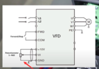
Let's assume the device being controlled is a VFD as in the attached picture or the PDF. Th one in the picture is straight forward.
The PDF extract is of a different VFD and that one has an option for 24VDC supply to keep the drive powered when the high voltage is turned off. It shows clearly that the grounds are separated, in other words the 0-10 volt loops should not be grounded to the same ground as the 24VDC supply power or anything as they are grounded inside the drive.
My question:
Why not ground the 0-10V to PE which would in effect mean that it would connect to the ground of the 24VDC because that one is usually grounded to a ground screw/chassis.
Thanks
I have seen many circuit diagrams of 0-10 volts wired to analog inputs of many devices and they all are pretty much identical.
Let's assume the device being controlled is a VFD as in the attached picture or the PDF. Th one in the picture is straight forward.
The PDF extract is of a different VFD and that one has an option for 24VDC supply to keep the drive powered when the high voltage is turned off. It shows clearly that the grounds are separated, in other words the 0-10 volt loops should not be grounded to the same ground as the 24VDC supply power or anything as they are grounded inside the drive.
My question:
Why not ground the 0-10V to PE which would in effect mean that it would connect to the ground of the 24VDC because that one is usually grounded to a ground screw/chassis.
Thanks