Continue to Site

Welcome to our site!

Electro Tech is an online community (with over 170,000 members) who enjoy talking about and building electronic circuits, projects and gadgets. To participate you need to register. Registration is free. Click here to register now.

  • Welcome to our site! Electro Tech is an online community (with over 170,000 members) who enjoy talking about and building electronic circuits, projects and gadgets. To participate you need to register. Registration is free. Click here to register now.

Wireless and hardware encoding

Status
Not open for further replies.

warp_kez

New Member
I have been searching the internet regarding some way of ensuring that the receiver gets the packets from the transmitter.

So far, it has been rather hit and miss. Sometimes it works, but generally it does not.

It has been suggested here and over at avrfreaks to use Manchester encoding, but I have not encountered much in the way of source code for this.

I am using a pair of attiny2313's and their UART ports. This is something else that I have read to be bad news, but examples of using something else have been elusive.

Additionally, I have read some thread here and at avrfreaks about using HT12D/E encoder chips, but that is about it.

Can someone please advise me, or even point me in the right direction?
 
Ok, I'll try and clear up some of this, I see this topic time and again here...
It's a little confusing to begin because it's not immediately obvious how to go about this...


Using NRZ (Non Return to Zero) like you are doing just now has two problems, firstly there is no common ground reference potential, it's wireless. Secondly, and more importantly, there is no synchronised clocking scheme. Manchester encoding solves this problem by embedding the clocking signal within the data stream.

Using NRZ to send one byte at a low data rate will most likely succeed, however sending several bytes will most likely fail. This is due to the clocking between sender and receiver not being synchronised. If the local clocks are off by even a smidgen, the clock error will be cumulative, the more data you send the worse it gets.

You will want to provide a mechanism for synchronisation of transmitter and receiver. You will also want to provide an error checking mechanism,but I'll get to that in a minute...

I find most folk don't understand the receiving end and hence have no clue how to go about transmitting data, so I'll describe the receiving end and leave the rest to you.


Quick note:

NRZ has bit periods, each bit takes a predefined time, sometimes called a bit slot, and only changes level or transitions at the bit period/slot boundary.

Manchester also has bit periods/slots, as in NRZ. However, level changes or transitions can occur at both bit period/slot boundary, and also in the middle of the bit period/slot. A level transition in the middle of the bit period is what dictates a 1 or a 0. A transition from low to high in the middle of the bit period defines a 1, likewise a transition from high to low in the middle of the bit period defines a 0.


For Clarity:
I prefer to call each bit time as the bit period, because that's exactly what we are working with, small periods of time stacked end to end, so from now on, I'll call them bit periods, and not slots. Also I will call level changes transitions, because that's what happens, the level transitions from one state to the other.


On to my example:

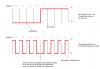
Lets assume that you want to receive a single byte of 0F in hex, or 15 in decimal (00001111 in binary). See the drawing.

Listen for a level transition, any level transition will do, then set your bit period timer to roll over just short of half your bit period. When it times out note the current level, if it's the same set your bit period timer again but for a little short of your bit period, if not go back to listening for a transition. The reason for setting the bit period timer for a whole bit period is because we are currently in the middle of our first detected bit period. Each successive roll over of our timer will land us in the middle of the next bit period ready to listen for a transition. Each transition effectively resets our local clock so that it never goes out of sync.

Essentially you are listening to the incoming data stream (a stream of bits) for two special bits. These special bits are nothing more than the level at the end of one bit period, and the level at the start of the next bit period.
What makes them special is that they will show you where the bit period boundaries are. These two levels can be either way round, i.e can both be high, or both be low, it makes no difference, we are only interested in finding two of the same level in our data stream.
These two levels mark a bit boundary, and we use this detected condition to set our bit period timer so that we land in the middle of our first detected bit period. After that each timer roll over lands us back in the middle of the next bit period etc, you then simply note each level when the timer rolls over, and wait until the level transitions, noting obviously which way round it went so you know if it was a 1 or 0 that you received.

Now, I mentioned earlier about synchronisation and error detection...

Synchronisation doesn't merely happen by detecting a bit period boundary, you need to prepare the receiver before dumping your guff to it. This is called a preamble. Now a preamble can consist of any bit level pattern, however, some bit patterns make more sense to use, otherwise you will be spending all your time checking if it was a valid byte you received as opposed to just getting your clocks in order.

Preambles are packets of bytes, i.e more than one or two bytes long, and usually consist of all 1's or all 0's.
The reason why you use all 1's or all 0's will be obvious if you look at my drawing. Each bit of an all 1 or all 0 bit pattern will always provide you with a transition at the bit boundary, i.e exactly opposite to what we would regard as a valid start of reception. You use this continuous bit level transition to synchronise your local clock to that of the transmitter.

Error correction is obvious, you need a way to know if you received a wanted byte, or the dog barking next door. The easiest way to do this is with a parity bit check, odd or even parity is optional.
Basically parity checking would be calculated by adding the number of 1's received in each byte. For even parity checking, the parity bit will be zero if the number of bits in the received byte was an even number. If it was an odd number, the parity bit would be a 1, i.e to make it an even number again.

Odd Parity checking is the opposite way round, i.e if the number of bits received in the byte were to be an even number, then the parity bit would be a 1 to make it an odd number, likewise if it was already an odd number of bits received, then the parity bit would be 0.

This type of error detection is only good on a per byte basis, to detect other anomalies in longer strings of bytes, you would send as the last byte or last couple of bytes, a checksum calculated at the transmitter. After performing your checksum calculation on the receiver, you would compare the value transmitted to that calculated, if the two are different then you have an error in transmission, if they are the same then the entire stream was received properly and is valid data. Most checksums use modulo schemes of one sort or another, but can be as complex as needed for your application.

It is also common to send the actual number of bytes being sent as the first byte or bytes, this allows you to prepare your buffers ready to receive the stream etc.

Basically, everything you can do with any other serial receiving scheme, can be done with a Manchester encoded stream, it's just a little more involved because you need to recreate the clocking locally.

I hope this helps out folks struggling to understand how Manchester schemes work :)
 

Attachments

  • Manchester encoding example.jpg
    Manchester encoding example.jpg
    48.6 KB · Views: 161
Last edited:
tunedwolf said:
Using NRZ to send one byte at a low data rate will most likely succeed, however sending several bytes will most likely fail. This is due to the clocking between sender and receiver not being synchronised. If the local clocks are off by even a smidgen, the clock error will be cumulative, the more data you send the worse it gets.

Well the post was so long and complicated, that I 'zoned out' in confusion :D

But this is completely wrong if you're refering to Manchester coding?, with Manchester there's no need for syncronisation between transmitter and receiver, bit time is irrelevent (within reason) as each individual bit effectively syncronises itself.

The only potential problem with longer packets is the greater possibility of errors in the data, nothing to do with syncronisation.

For the OP, dump the hardware UART, you can't correctly do Manchester through a UART.
 
I guess it's easy to "zone out" with such a long winded attempt at an explanation.

What bit is completely wrong ?, I did mention that in Manchester encoding that the clocking scheme is embedded into the data stream. You are correct, each bit effectively provides it's own clock, but I would have thought that obvious from the drawing and the explanation.

And yes, you are also correct, it is a lot more difficult to use a UART for Manchester, but not impossible, some of the systems I work on use Philips or Siemens micros that implement Manchester encoding schemes using the on board UART.

Instead of criticising me for my attempt to help the op, why don't you post an explanation and a drawing to clear things up, as I'm obviously mistaken...and perhaps clear things up for the op while you're at it.

rgds
 
Last edited:
tunedwolf said:
I guess it's easy to "zone out" with such a long winded attempt at an explanation.

What bit is completely wrong ?, I did mention that in Manchester encoding that the clocking scheme is embedded into the data stream. You are correct, each bit effectively provides it's own clock, but I would have thought that obvious from the drawing and the explanation.

The line I quoted:

"This is due to the clocking between sender and receiver not being synchronised. If the local clocks are off by even a smidgen, the clock error will be cumulative, the more data you send the worse it gets."

And yes, you are also correct, it is a lot more difficult to use a UART for Manchester, but not impossible, some of the systems I work on use Philips or Siemens micros that implement Manchester encoding schemes using the on board UART.

But not correctly, a UART is completely fixed as to how it sends the data, and can't generate correct Manchester coding - and receiving correct Manchester is completely out of the question.
 
Nigel , can i send a byte using UART hyperterminal , then get it , then remove the start / stop bit , and then send it using manchester encoder ?
 
ahmedragia21 said:
Nigel , can i send a byte using UART hyperterminal , then get it , then remove the start / stop bit , and then send it using manchester encoder ?

Yes, that's normally what you would do to get Manchester from a UART - RFSolutions even make chips that do it for you (RF600 I think?).
 
Nigel Goodwin said:
The line I quoted:

"This is due to the clocking between sender and receiver not being synchronised. If the local clocks are off by even a smidgen, the clock error will be cumulative, the more data you send the worse it gets."


But not correctly, a UART is completely fixed as to how it sends the data, and can't generate correct Manchester coding - and receiving correct Manchester is completely out of the question.

I wasn't talking about Manchester encoding at that point...I was referring to NRZ, or a straight serial stream from a UART. Further I go on to define each encoding scheme's general characteristics in my quick note, so folks would know the differences between them.

I don't think I mentioned that the Manchester schemes used were fully compliant, they are schemes, they do however work in practise, as does many other serial protocol implementations that are out of compliance.

Anyway...I'll chalk this up to experience, and brush up on my book writing skills while I await your explanation and drawing ;)
 
ok...I'll bite...

After being more than a little confused at first with where your tutorial was actually located, tut12 if I'm correct, on the second layer into your site. I then immediately tune out myself by taking the link you provide at the bit where you state that you are using someone else's code for the encoding & decoding.

I actually missed the bit where I was able to download your example source the first time round, and had to go back to get it.

I immediately think to myself whilst reading through your source that the op never mentioned that he was using a PIC micro, and thought that he might be even more confused by it. I never mentioned your tutorial to the op because of this fact in the first place, he is using ATTiny's according to his post.

Anyway, I'm gonna let this go now...there's no point in wasting any more time scoring points and measuring the length of our clock pulses, so to speak, against each other.

rgds
 
Appologies for the delay in responding.

I have been experimenting more, and found a couple of things out:
1) Do not slave the transmitter and receiver circuits to the same power supply
2) I have to send the command at least 3 times to ensure it is received.

As it is, it is working, but I am reading more and more on this so I can improved the effectiveness of my project.
 
wireless

warp_kez said:
I have been searching the internet regarding some way of ensuring that the receiver gets the packets from the transmitter.

So far, it has been rather hit and miss. Sometimes it works, but generally it does not.

It has been suggested here and over at avrfreaks to use Manchester encoding, but I have not encountered much in the way of source code for this.

I am using a pair of attiny2313's and their UART ports. This is something else that I have read to be bad news, but examples of using something else have been elusive.

Additionally, I have read some thread here and at avrfreaks about using HT12D/E encoder chips, but that is about it.

Can someone please advise me, or even point me in the right direction?

Why not just use the HT12D/E encoder chips? It's real easy, and reliable. And besides the cost is minimal.

What wireless modules are you using? I did a project using a couple of tiny2313's and the TLP/RLP 434A modules with and without the HT12D/E encoder chips and it works very reliably with the encoder/decoder chips.
It does not work very reliably without the encoder/decoder chips. (I did not use manchester encoding)

If you are looking for source (in asm) for manchester coding you can try looking avr datasheets avr410 & avr415. At the least, they will give you some ideas. I believe you will find them on avrfreaks, OR the atmel website.

Also using the uart is not as efficient as bit-banging the serial data. You can also get that code on avrfreaks as well. Try looking for avr305.asm.

Best regards.
 
To the OP.

From reading your post, I assume that you not only want to find an effective way to send data over RF (channel coding like manchester etc..) but also some form of error detection/correction?

For microcontrollers FEC (forward error correction) can be tricky, and pretty useless with simple codes like the [12,8] hamming...as you're sending more bits and so increasing the chances of errors. In this day and age it might be prudent to buy pre-made modules with digital stuff built in. I have had enormous success with 'easy radio' modules. You can check out https://www.lprs.co.uk I would also recommend sparkfun (https://www.sparkfun.com). They have many 2.4Ghz modules from NORDIC which have built in automatic resend, CRC, sync etc..

If however you wish to use your current modules, and DIY the situation, a UART can be used to send manchester coding, albeit a bastardised version..but a hardware UART cannot recieve it alone. It requires some software to directly look at the stream to sync to it..and then its probably just easier to do the whole recieve part in software anyway - the atiny's are more than fast enough.

RF comms is generally hit and miss most of the time anyway, what with DC balancing, syncronisation, as well as an ample preamble to 'wake up' the reciever.

For a simplex system (one way) there really is no way for the Tx to know whether the reciever has got the correct data, if at all. But of course, duplex systems are more expensive.

Any specific questions? or are you still tinkering?

Blueteeth
 
Last edited by a moderator:
Status
Not open for further replies.

Latest threads

New Articles From Microcontroller Tips

Back
Top