Continue to Site

Welcome to our site!

Electro Tech is an online community (with over 170,000 members) who enjoy talking about and building electronic circuits, projects and gadgets. To participate you need to register. Registration is free. Click here to register now.

  • Welcome to our site! Electro Tech is an online community (with over 170,000 members) who enjoy talking about and building electronic circuits, projects and gadgets. To participate you need to register. Registration is free. Click here to register now.

Will this work? (driving 7-seg display with MCU)

Status
Not open for further replies.

toohyetoreply

New Member
Hi,

I made a couple of posts on this already but I finally have a schematic drawn up. I'm just posting it here in case there's something wrong with it.

I'm trying to drive these LEDs with a microcontroller
**broken link removed**


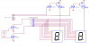
Here is what I have come up with.
**broken link removed**

The microcontroller uses the select lines that top to select which digit will be turned on. Then it uses the a-dp lines to control which segment will be turned on. I'm using the mosfets as switches but I'm worried that they won't work as I want them to. There is 12 volts over the whole thing and the LED segments will take 11 volts of it, so there will be 1 V across the resistor and the 2 mosfets...*confused*

I'm also thinking of doing it like this:
**broken link removed**

And hooking it up directly to the MCU. The main thing i'm worried about this one is connecting the 12V to the MCU. To turn the LEDs off, the MCU will output 5V and there won't be enough voltage drop across the LEDs to light them, It will be like connecting to an open circuit so it shouldn't matter if there's 12V on the other side, right?

If the LEDs are on, the MCU will output 0V, but the LEDs will drop 11V, so there'll only be 1V connected to the resistor connected to the MCU pins, so I don't see how that can damage the MCU either. The only thing I have to worry about is the decimal points which won't drop 11V but probably around 3.7 volts, but then that would be dropped across the resistor anyways.

What do you guys think?
 
Neither circuit will work properly. You need P channel FETs to drive the CA of the 7seg displays. The Vgs drop of an N channel FET would be too much. But using P channel FETs means you'll have to add an additional 2 N transistors to drive the gates of the P channel FETs. It is almost worth your while to direct drive the 7seg displays, especially if you will have only two digits. Also note that the dp segment will need a higher resistor value because there are less LEDs in series for that one.
 
Neither circuit will work properly. You need P channel FETs to drive the CA of the 7seg displays. The Vgs drop of an N channel FET would be too much. But using P channel FETs means you'll have to add an additional 2 N transistors to drive the gates of the P channel FETs. It is almost worth your while to direct drive the 7seg displays, especially if you will have only two digits. Also note that the dp segment will need a higher resistor value because there are less LEDs in series for that one.

Yes, I just realized after posting that Vgs is going to be negative. I haven't learned anything about PMOS yet besides the fact that "they're the opposite of NMOS". I don't know what you mean by "you'll have to add an additional 2 N transistors to drive the gates of the P channel FET's".

Sorry, I only drew 2 digits to save space but I'm going to have 6 (I drew the selector lines for all of them).

I'm going to be using a AVR. Possibly an ATMEGA48. How can I directly drive the displays with that? The displays need 11 volts and the MCU can only supply 5.

So....as of now I'm pretty stuck on this. I will try reading into P-channel FETs or something. Can anybody provide some example circuits I can use?

Thanks guys.
 
If keeping things simpler and staying with not having N-ch FETs, there could do with being a bit more voltage drop in the LED current limit resistor. 2 or 3 V would be better. The only way to do that is raise the voltage up from 12 V to say 14 or 15 V. But not too high, the uC doesn't really want to see a voltage higher than 5 V on an output. Without FETs, the forward voltage drop of the LEDs is relied on to block this voltage enough so that it doesn't reach the output. If you can't solve this, you'll have to add a load of N-ch FETs.

The P-fets need a bit more drive circuit adding. To turn on a p-fet, you pull the gate downwards away from the source voltage (presently 12 V) by at least 4 to 5 V. Unfortunately in the current schematic the uC output literally "doesn't swing it".

As kchriste says, circuit needs adding. An NPN needs adding to pull the gate down, this NPN base is driven high by the uC (via resistor).
 
Last edited:
Sorry, I only drew 2 digits to save space but I'm going to have 6 (I drew the selector lines for all of them).
You might want to look into FET arrays for the NFETs, but discreet devices may be easier to find.
Can anybody provide some example circuits I can use?
Here ya go:
 

Attachments

  • 7seg.png
    7seg.png
    56.8 KB · Views: 883
Wow, thanks a lot.
Couple of more questions,
For the P-channel FET, can I use the BS250? I just googled "2N7000 complement" and that is what I found.

The resistor that is "1K-10K", that is some sort of pullup resistor? Is there anything to take into account when choosing what value it should be? Using 10K would mean there would be less current flow and it would use less power, so should I just use that?

And one last thing...I've heard my professor say "NMOS" and "PMOS". Is this the same as N-channel FET and P-channel FET?

Thanks again.
 
The BS250 would be OK for just 2 digits, but for 6 digits you'll need to run the LEDs at a higher peak current than normal because of the 1/6th duty cycle will make the average current through them lower. ie: 10ma x 8_seg x 6_digits = 480ma peak anode current. So the RDS(on) of 5Ω for the BS250 is too high and would drop about 2.4V at that current. A FQP27P06 will work though it is a bit over spec'd. It's advantage is a very low RDS(on) of 0.07Ω, it can be used for other projects, and it's pretty cheap at around $1US. You'd need to change the 220Ω resistors to 33Ω to maintain an average current of 10ma in the LEDs when multiplexing six digits. You could run them at a lower current, but they may be too dim then. That would be recommended anyway when you are debugging code because one digit could be stuck ON for extended periods until the code is running correctly.

The resistor that is "1K-10K", that is some sort of pullup resistor? Is there anything to take into account when choosing what value it should be?
Yes, it is a pullup resistor. The lower the value, the more current that will be consumed, but also the faster that the PFET will turn off. It depends on how fast you want to multiplex and the gate capacitance of the PFET.

I've heard my professor say "NMOS" and "PMOS". Is this the same as N-channel FET and P-channel FET?
Yes. Though the term "NMOS" and "PMOS" can also refer to types of logic chips that use all N-channel FETs or P-channel FETs internally.
 
Last edited:
Oh okay, so basically if I'm running the LED's at 1/6th of the time, I should run 6x more peak current through them to maintain the same average current.

I'm going to take your word on the parts and get the FQP27P06 and 33Ω resistors (and maybe 220Ω while testing).

I've read multiplexing at 100 Hz is a reasonable rate. I was looking through the data sheet and the only thing I found about switching time was for a gate resistor of 25Ω. Is there a way to figure out the switching time with R=10K? I guess the main concern is so that the transistors will switch fast enough so that no two are on at the same time and burn the MCU. Should I leave some clock cycles between switching? (I'm probably gonna be running at 32.768 Khz).

Thanks so much for all the help! I guess I will now move on to designing the buttons, alarm, etc, which shouldn't be too hard.
 
I'm going to take your word on the parts and get the FQP27P06 and 33Ω resistors (and maybe 220Ω while testing).
Remember, the 33Ω is for a 13V supply assuming the voltage drop of the LEDs is really 11V as stated in the Ad.
Is there a way to figure out the switching time with R=10K?
You could simply use the RC time constant of the gate capacitance and R. It won't be entirely accurate, but the RC time constant will swamp any other factors anyway. So for a worst case of Ciss = 1400pf and VGS(th)=2V with a supply voltage of 13V and R = 10K the turn off time would be apx 26.6uS. You could use a 1K pull up to shorten this to 2.6uS since only one 1K resistor will have 13V across it at a time at a total cost of 13ma. Nothing compared to the 480ma that the displays will collectively draw.
I guess the main concern is so that the transistors will switch fast enough so that no two are on at the same time and burn the MCU.
You won't damage the MCU. The worst that'll happen is a bit of ghosting.
Should I leave some clock cycles between switching?
Yes, turn off all the segment lines, wait one cycle (A single NOP at 32Khz [30uS] should be long enough) then change digit select lines, wait one cycle, output seven seg code, delay to display and repeat. This will take care of any ghosting and you can probably get away with 10K pullups.
 
Last edited:
Status
Not open for further replies.

Latest threads

New Articles From Microcontroller Tips

Back
Top