Continue to Site

Welcome to our site!

Electro Tech is an online community (with over 170,000 members) who enjoy talking about and building electronic circuits, projects and gadgets. To participate you need to register. Registration is free. Click here to register now.

  • Welcome to our site! Electro Tech is an online community (with over 170,000 members) who enjoy talking about and building electronic circuits, projects and gadgets. To participate you need to register. Registration is free. Click here to register now.

Will this work as a buck converter?

Status
Not open for further replies.

riccardo

Member
Hi,

I'm trying to make a simple DC-dC converter to step down a voltage. I want to use a buck converter method (see below).

Buck converter - Wikipedia, the free encyclopedia

The above shows the switch (transistor) in a different place to what I was hoping to do. I hoped to just use an N-type MOSFET like in the attached diagram. Would that work?

If not, can I just use a P-type and place it where it is on the wiki article?
 

Attachments

  • buck.jpg
    buck.jpg
    57.7 KB · Views: 2,552
Last edited:
Hi,


The better way is if you move the inductor into the other lead (between upper mosfet terminal and cap lower terminal) and you take the output from between Vcc and the bottom of the cap. In other words, if you use an N channel instead of P channel then you reference your output to Vcc instead of ground.
Whichever way you do it you have to take the output from across the cap, not referenced to ground. When we put the switch into the ground lead we loose the ground reference. The way it is drawn in that circuit there will probably be more noise generated though because both leads of the output have to hop up and down rather than be somewhat smooth all the time.
 
Last edited:
Use a PMOSFET as the switch in the wiki circuit. The gate of the FET must be switched between ground and the input voltage (VCC) for proper operation.

If you wanted to use a grounded source NMOSFET as a switch, that would work in a flyback type of converter. But that requires an inductor with two windings.

If you want to determine how a circuit will work, you should try simulating it in LTspice. It will show you the circuit operation without having to build the circuit.


Hi Carl,


Well actually the NMOSFET will work in a buck converter exactly as he has drawn, it's just that you have to take the output then from Vcc and the bottom of the cap rather than from ground and the top of the cap as with a PMOSFET. It does work.
As i mentioned above however, it's better to move the inductor into the other lead (right off the top of the NMOSFET) as that will be less noisy.
Try a simulation and see how well it works, but remember that the output is Vout=Vcc-VcapBottom and not the usual Vout=VcapTop-Ground.
Of course this can not be used if he requires a ground referenced output voltage.
 
Last edited:
Thanks!

The load current is going to be different to the source current right? So how might I take a measurement? A resistor between source and GND (see attatched) would allow me to measure the input current with my circuit by linking the points marked "CurrentSignal" and "GroundCurrent". Since this is a ground reference measurement, it is simple. I'm not sure how I might feed a signal from a resistor in series with the load to the point marked "CurrentSignal".
 

Attachments

  • buck2.jpg
    buck2.jpg
    100.2 KB · Views: 653
Hi again,


If you wanted to use the source current measurement to control the output current you would also have to take into account the power supply voltage (Vcc) as the current would vary as Vcc varied too say with load. Probably a better way is to use a differential amplifier or other configuration to measure the output current directly and that way you get good control, unless of course you dont need too much accuracy. Sometimes peak source current measurements are used to control the output voltage but that is usually when the accuracy does not have to be too perfect. There is a relationship there but it tends to vary a little with other normally changing parameters. For a fixed output load a fixed peak current is sometimes used, again with some loss of accuracy of the set point over temperature.

You also have to be aware of the input offset of the op amps, and with your choice of part the offset can be as high as +/- 0.012v, which is quite high these days and im not sure if that would work very well unless you went through some sort of calibration phase for this design. Also, with a sense resistor as low as 0.001 ohms it may be difficult to measure the current unless the current is fairly high. We'd need to know your required output current to specify this value.

So in other words it would help if you could state your required accuracy (roughly) and your output current, output voltage, and supply voltage. For example, if you want 1 amp output would it be ok if it was 0.9 amps instead, or would 0.99 amps be required? That's 10 percent accuracy vs 1 percent, and of course 1 percent will be harder to achieve than 10 percent accuracy.

Also, what kind of speed of response do you need here? For example, if either Vcc changed or the load changed how fast would your output have to readjust to the correct output again? Many devices dont need super fast response such as battery chargers, but other types of loads sometimes do.

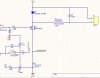
I noticed you have a 10mH inductor there, is that large value really needed because the switching frequency is relatively low or can you use a smaller value?
 
Last edited:
Thanks for your reply!

I'm trying to make a constant (average) current supply to a load which may vary in resistance. Could be from 10A to 40A. Regulating the average current, 10% is ok, response time can be reasonably slow, although it would be good if it was fast enough to deal with an accidental short circuit to save the transistor. The output does not need to be smoothed at all really. Supply will be 12V DC. The inductor value is just random at the moment, I was planning to experiment with it. Was thinking of frequency range from 100Hz to 1kHz approx.

It is based on this diagram, I just want to add the buck converter to it.
https://www.hhocarfuelcell.com/pwm-circuit/constant-current-pwm.php
 
Last edited:
Hello again,

Ok then it sounds like measuring the average current in the source lead would probably work ok for your application. You have to average it, but i think you got that part already. Since your external signal generating the pulse timing is being controlled you can use the duty cycle to calculate the output current from:

Vout=D*Vin
Iout=Vout/RL
Is=D*Iout

where D is the duty cycle (0 to 1) and Is is the average source current. but since we dont know what RL is we might use:
Is=Vout/Vin*Iout

and this requires a measurement of Vout and possibly Vin if Vin changes a lot too during normal operation.

You could easily run the circuit through a few tests once it is built and using some known output loads calibrate the control signal to compensate for any of the other static circuit values such as the inductor ESR. That would get even better accuracy for little trouble.

I see now why you want to use a 0.0015 sense resistor, but the op amp chosen may give you a problem because at 10 amps the voltage across that resistor is only 15mv and that could easily be equal to the input offset voltage of that op amp. Thus, this could lead to a 100 percent error in set current unless the circuit is somehow calibrated and the input offset voltage does not vary too much with temperature. There are quite a few op amps out there these days with much better specs then that one has so you may wish to reconsider the choice of op amp for the current measurement, or else provide for some sort of input offset adjustment perhaps.
 
Last edited:
That's great, thanks, I will look at using a different op-amp too. I'm just making a test circuit first as I expect I will need to tweak things later and maybe eventually interface with a microcontroller.

Thanks for all the help!
 
Status
Not open for further replies.

Latest threads

New Articles From Microcontroller Tips

Back
Top