Continue to Site

Welcome to our site!

Electro Tech is an online community (with over 170,000 members) who enjoy talking about and building electronic circuits, projects and gadgets. To participate you need to register. Registration is free. Click here to register now.

  • Welcome to our site! Electro Tech is an online community (with over 170,000 members) who enjoy talking about and building electronic circuits, projects and gadgets. To participate you need to register. Registration is free. Click here to register now.

Will this current limiting funtion work?

Status
Not open for further replies.

RedValley

New Member
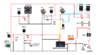
I wanna make a LAB BENCH POWER SUPPLY using LM317 with CV & CC
Can anyone plz inform me how this circuit current limiting function work? It says it can limit current 0 - 10A. As I'm a student I don't know actually will this circuit can limit current or not. It will be helpful if you kindly let me know
I got this from YouTube
 

Attachments

  • Diagram.png
    Diagram.png
    271.1 KB · Views: 218
Everything in that circuit looks like it would be correct.
Hey this circuit works. CV has coarse adjustment and I know how to do fine CV adjustment. But can you help me to do fine CC adjustment? CC adjust coarse ( I tried 1A load using lamp, then adjust CC knob it shows : 1A , 700mA, 500mA, 200mA then 0) but how can I do fine CC adjustment ?
 
The current circuit is plain weird..
It has no actual sensing across the series power resistors, and the voltage regulation does not allow for the voltage drop across those so the output voltage is not actually stabilised, or the true output being displayed on the meter.

You could substitute something like this for the 317 & transistors etc., in that, keeping the meter and other voltage regulators. It shoud work far better:
Thank you, I'll see it
 
The current circuit is plain weird..
It has no actual sensing across the series power resistors, and the voltage regulation does not allow for the voltage drop across those so the output voltage is not actually stabilised, or the true output being displayed on the meter.

You could substitute something like this for the 317 & transistors etc., in that, keeping the meter and other voltage regulators. It shoud work far better:
How much current can it provide?? Can I use transistor for more current ?
 
Having looked at that bizarre circuit of a power supply, I believe that it was intended as a (rude) battery charger.

There are diodes on the +ve output connection, those diodes are not inside a feedback loop to give a "constant voltage" function.

The two current sharing resistors on the emitters of the TIP3055 transistors are not inside a feedback loop to give a "constant voltage" function.

There is no obvious current sensing of the output current to give a current limit function.

To me this appears to be a bad circuit, dump it and find a better one.

JimB
 
Sonce none of the pins on any of the parts are identified, the drawing (note: *not* schematic) is almost impossible to decipher. If you draw a actual schematic, you will see many of the problems.

Note - crossed wires do not indicate a connection; they indicate a mistake waiting to happen. Connection dots indicate connections.

ak
 
How much current can it provide?? Can I use transistor for more current ?

The PNP power transistor at the input of the LM317 provides most of the current - the one given, MJ4502, is rated at 30A so shoudl be adequate.

The real limiting factor is power dissipation; the transistor has to drop the difference between the input and output.
With a high input voltage and low output voltage, eg. 30V and 5V, the transistor would need to dissipate around 25W per amp of load.

If you want a high output voltage capability, I'd suggest using a centre tapped transformer and full bridge rec, so you can switch between eg. centre tap and full winding for two different input voltage ranges.
eg. A 12-0-12 transformer could give roughly 18V / 36V rectified.
 
Status
Not open for further replies.

Latest threads

New Articles From Microcontroller Tips

Back
Top