Electro Tech is an online community (with over 170,000 members) who enjoy talking about and building electronic circuits, projects and gadgets. To participate you need to register. Registration is free. Click here to register now.
Welcome to our site! Electro Tech is an online community (with over 170,000 members) who enjoy talking about and building electronic circuits, projects and gadgets. To participate you need to register. Registration is free. Click here to register now.
If you are lucky, you could probably transmit a maximum of 12 inches with a 9V battery.
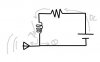
Transmitters have oscillators. Your circuit does not show one. You need capacitors. An active device (transistors as the most common one) would help too.
there are ultra simple transmitters on the net. Look on discovercircuits.com
That is called a tank circuit. What basically happens is that current bounces back and forth between that capacitor and inductor. The current gets stored in the capacitor's electric field, then it leaves the capacitor and gets stored in the inductor's magnetic field.
Theoretically, this process could go on infinitely. Unfortunately, that resistor represents losses in the system, whether they be inductive losses (the magnetic energy transfers to other metal objects around it), resistive losses (the resistance of the conductor), etc.
The number of times that it bounces back and forth per second is the frequency: If it bounces back and forth 100,000,000 times per second, it's frequency is 100MHZ.
Mstecha is right though, that is not a transmitter.
Hi Chui,
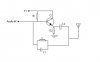
I don't think your circuit will oscillate. An oscillator needs a gain of more than one. Your emitter-follower has a gain slightly less than one.
Why not use a standard Colpitts or Hartley RF oscillator circuit?
Hi Chui,
An oscillator doesn't work with majic, it works by feeding the output of an amplifier back to its input with the proper phase for the feedback to be positive, and enough level for oscillation to start and continue.
If the amplifier is an emitter-follower with a gain of slightly less than one, there isn't enough feedback level to start oscillation and not enough to maintain oscillation. With some gain in the oscillator's amplifier, at the beginning the circuit's noise is amplified, then fed back at a higher level to the input at the frequency of the tuned circuit and keeps on amplifying and feeding back until the output is at full level with a signal without much noise.
I don't analyse standard circuits, I just use them. If you want to analyse them then do a Google search for RF Oscillator and you will find many tutorials.
A grandfather clock is a mechanical example of an oscillator.
A pendulum on its own oscillates if given a push, but it is a damped oscillation, ie. it gradually looses energy and eventually stops swinging.
So it needs an energy source such as a weight hanging from a chain and a mechanism to give the pendulum a kick at the right moment and of sufficient energy to maintain its kinetic energy. This is positive feedback.
As Audioguru said, an emitter follower has a voltage gain of slightly less than one. So it cannot keep the tuned circuit oscillating. So the TC gradually looses energy and stops, ie. it is a damped oscillation.
To keep it oscillating, you need a loop gain of one so that the energy lost per cycle is exactly replaced from the energy source.
If the loop gain is greater than one, it will oscillate, but the waveform will be more like a square wave rather than sineusoidal.
Hi Len,
The tuned circuit filters out most harmonics caused by overdrive. Overdrive is used so that the oscillator starts oscillating quickly, and so that a gain of slightly more than 1 is guaranteed with the worst tolerance combination of the parts that determine gain. :lol:
It should be mentioned that the Colpitts oscillator uses an emitter follower. The voltage gain is provided by driving a "tap" on the tank circuit with the emitter. The emitter follower provides current (and power) gain, allowing oscillation.
The tuned circuit filters out most harmonics caused by overdrive. Overdrive is used so that the oscillator starts oscillating quickly, and so that a gain of slightly more than 1 is guaranteed with the worst tolerance combination of the parts that determine gain. :lol:
Yep, after 4 pages of trying to explain to someone who "lern'd" transistors, how to make a transistor drive a relay, I also said in frustration, "I could tell that you are a noobie because you don't know anything about voltage, current, resistors and relays."
That's why I never became a grade 7 teacher.
Hi Len,
I have a 3-buffered-stages phase-shift oscillator that clips its output due to excessive gain, for fast starting and quick frequency changes. By the time its 3 lowpass filters (phase-shift stages) purify the clipping, its distortion is 0.07%. Its amplitude always snaps into the correct amount. :lol:
Any particular reason not to go for a Wein bridge configuration with a non-linear element in the gain determine stage, like a bulb, Jfet or zeners, so that the gain is just spot on and the output wave does not clip in the first place?
Is Wein bridge slow to settle with frequency changes?
Any particular reason not to go for a Wein bridge configuration with a non-linear element in the gain determine stage, like a bulb, Jfet or zeners, so that the gain is just spot on and the output wave does not clip in the first place?
Is Wein bridge slow to settle with frequency changes?
But I just want to find out whether there are other reasons as he hinded that low distortion is also what he is after. The Wein bridge oscillator with a light bulb gives very low distortion then using jfets or zeners as gain control element.
Hi L. Chung,
I (bounce, bounce) also have (bounce, bounce) a Wien bridge oscillator (bounce, bounce) that I built long ago. First I tried a lightbulb, then a Fet, then diodes and LEDs, then some opto-Fets and now back to a Fet again to try and stop the darn bouncing. At my very 1st job there was an original old sine-wave generator made by Mr. Hewlett and Mr. Packard with a huge lightbulb in it. He, he. :lol:
My extremely low distortion oscillator uses a CD4018 to make a stepped 10-times oversampled sine-wave followed by a very steep switched-capacitor lowpass filter IC then a 2 pole Butterworth lowpass filter to get rid of the clock remnants.
My distortion analyser also uses switched-cap lowpass filters and also a switched-cap notch filter.
All the switched-cap filters and notch filter use the same clock for solid sync. I planned the oscillator to be sweepable with a 74HC4046 phase-locked-loop and counters for the clock, but gave-up when the PLL gave jitter in its output frequency due to the wide ranges I chose (20-2kHz, 200-20kHz). I can't measure the distortion of the oscillator since it is buried in noise at -100dB (0.001%). :lol:
You must use the light bulb on an oscillator of 20Hz, no wonder.
audioguru said:
My extremely low distortion oscillator uses a CD4018 to make a stepped 10-times oversampled sine-wave followed by a very steep switched-capacitor lowpass filter IC then a 2 pole Butterworth lowpass filter to get rid of the clock remnants.
How did you manage to get those odd ball resistor values? I was told if the resistor values are as designed, the first harmonic would be the 19th(at -26dB) for a ten stage wave generator.
audioguru said:
My distortion analyser also uses switched-cap lowpass filters and also a switched-cap notch filter.
That's why you need such low distortion level because it is to be use as the frequency source for testing.
audioguru said:
I planned the oscillator to be sweepable with a 74HC4046 phase-locked-loop and counters for the clock, but gave-up when the PLL gave jitter in its output frequency due to the wide ranges I chose (20-2kHz, 200-20kHz).
I once tried a PLL using 4046 to give me range of 200Hz to 1MHz because I want to use it as a X100 frequency multiplier. As you said, too much jitter to the point that is is unusable.
audioguru said:
I can't measure the distortion of the oscillator since it is buried in noise at -100dB (0.001%). :lol:
How did you manage to get those odd ball resistor values? I was told if the resistor values are as designed, the first harmonic would be the 19th(at -26dB) for a ten stage wave generator.
I used a 12V supply to keep down the output resistance of the CD4018. The resistors are a matched pair (I selected them to be the same) of 47k and another matched pair of 75k, 5% 1/4W metal film.
I simply scaled-up the 1% resistor values recommended by Don Lancaster in his Cmos Cookbook. He says with a 10-steps wave, the 9th and 11th harmonics are down to 1/10th or about -20db. I matched the resistors for low 2nd, 4th and other low frequency even-harmonics. :lol:
This site uses cookies to help personalise content, tailor your experience and to keep you logged in if you register.
By continuing to use this site, you are consenting to our use of cookies.

")