Continue to Site

Welcome to our site!

Electro Tech is an online community (with over 170,000 members) who enjoy talking about and building electronic circuits, projects and gadgets. To participate you need to register. Registration is free. Click here to register now.

  • Welcome to our site! Electro Tech is an online community (with over 170,000 members) who enjoy talking about and building electronic circuits, projects and gadgets. To participate you need to register. Registration is free. Click here to register now.

Wii u with no power

Status
Not open for further replies.

sidbroad

New Member
Hi, I'm very new to this sort of stuff and would like to try and repair a Wii u console just for fun really and learn new skills. I've watched alot of tronixfix on youtube alot as I found it interesting and think it's time to have ago myself.

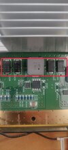
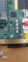
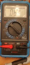
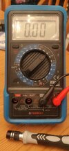
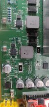
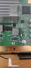
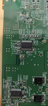
The console has been tested with a known working power supply and it's still dead. I've stripped it down the motherboard and have tested all the fuses I think. Here is where my problem is tho. I found 4 chips which I'm not to sure what they are but 2 of them beep and the other 2 don't. Here is a picture of them if anyone can identify them for me and if I'm on to something or if I'm barking up the wrong tree. The 2 on the left beep but the 2 on the right don't. Any pointers are welcome, thanks
 

Attachments

  • IMG_20220413_185811__01.jpg
    IMG_20220413_185811__01.jpg
    2.1 MB · Views: 254
Here is a pic of where the power comes in. Any advice on where to start is welcome.
 

Attachments

  • 16498740657044857265092309005440.jpg
    16498740657044857265092309005440.jpg
    2.2 MB · Views: 213
There is a fuse immediately behind the yellow connector - is that OK?

The black "chips" in the first photo are capacitors, so any readings across them will depend on what they connect to in the rest of the machine circuit.
 
I think this is probably to advanced for me. Been reading other threads and it seems to be a waste of time without the schematics. Is that about right lol?
 
OK, with power on, what voltage is there across one of the caps to right of centre and what voltage across one left of centre (in the first photo)?

The right side probably has the power adapter voltage & left side either 5V or 12V??
 
DC voltage, the 20V range (or 200V if that shows overrange); the upper right quadrant - the dotted equal sign indicates DC, the lower right with ~ is AC volts.

And make sure the test leads are in the COM(-) and V(+) sockets when measuring voltage; if you leave one in the Ohms/mA socket it may damage the meter or whatever you connect it to.
 
With this setting in picture. The left of centre cap has fluctuations of 0.02 to 0.05. the right of centre cap is doing the same between 0.02 and 0.07.
 

Attachments

  • 1649883113869411247748795207706.jpg
    1649883113869411247748795207706.jpg
    2.9 MB · Views: 177
So I've either done it wrong or there is no power going through these caps? I put the the leads one either side of each chip and got a really low readings that went down to 0 sometimes even. Should it be 12.0 rather than 0.05? Im starting to think that power isn't getting through the big yellow power block that the power supply plugs into.
 
Im starting to think that power isn't getting through the big yellow power block that the power supply plugs into.
Looking again at the photos, it appears there are two switched-mode regulators; check for voltage across the round aluminium cap that's bottom centre in the first photo?

Put the negative lead on the metal lower edge of the PCB and test from the fuse next to the power socket and the upper terminal of that capacitor?
 
The fuse next to the power socket shows at 14.96 on both sides of the fuse. The upper part of the cap is also at 14.96.
 
OK, progress!
Next steps:
Check voltage (from ground; the metal edge) to both sides of C1394 and to the upper pins on the large 8 pin IC (actually a power FET) just above it.

Can you also take a better close-up photo of that overall area, that has the part numbers on the components clear?
 
Ok, C1394 is not giving a reading and the 8pin above is also not giving a reading. This seems like we've found the problem?
 

Attachments

  • 16499260701823520012213223230726.jpg
    16499260701823520012213223230726.jpg
    2.8 MB · Views: 199
  • 16499261040757942857519688822511.jpg
    16499261040757942857519688822511.jpg
    2.4 MB · Views: 209
Don't know if this mean anything but the fuse here is beeping both ways on continuity?
 

Attachments

  • IMG_20220414_130804__01.jpg
    IMG_20220414_130804__01.jpg
    3 MB · Views: 212
Can you get the number from IC "U103" on the underside? That is what controls the power FET.
 
Status
Not open for further replies.

Latest threads

New Articles From Microcontroller Tips

Back
Top