Continue to Site

Welcome to our site!

Electro Tech is an online community (with over 170,000 members) who enjoy talking about and building electronic circuits, projects and gadgets. To participate you need to register. Registration is free. Click here to register now.

  • Welcome to our site! Electro Tech is an online community (with over 170,000 members) who enjoy talking about and building electronic circuits, projects and gadgets. To participate you need to register. Registration is free. Click here to register now.

Wideband matching an electrically short bowtie antenna; 50 ohm, 434 MHz

kellogs

Member
This is the technique applied so as to obtain a wideband matching + balun for a bowtie antenna.

I have run a simulation:
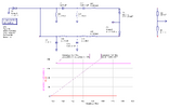
simulation-50%.png
The two 43.3 nH inductors are there to cancel each -j*118 antenna arm reactance. Does it make sense ?

I have remeasured the antenna + caps / inductors populated with my nanoVNA and have found R - j*20 ohm. R was in the 10 - 20 ohm range, can't remember, anyway, less than 50. i have made approximations for all of the matching network's elements, i.e. precise values were used for only 8 pF, 24 pF and 7.5 nH. What should I do next to at least get that reactance closer to zero ? The antenna is very deaf currently.

Thank you
 
You say wideband but list a single frequency?
It you mean signal bandwidth, that will be small compare to the carrier frequency and antenna matching range. The entire ISM band is less than 2MHz wide.

A bowtie is presumably cable fed? I'd stick with a stub match, half wave cable balun or just common mode choke. Those are all effective and well proven methods.
One example:

Look in the ARRL handbook or similar for others.
 
The antenna + matching network all live on a PCB. It is electrically small for the frequency and its measure impedanced in one spot was 14 -j*236 ohm.

It will to get detuned when placed in other spots, i.e. impedance variation of +/- 5%, so I wanted at least the matching network to be forgiving of that.
 
You say wideband but list a single frequency?
It you mean signal bandwidth, that will be small compare to the carrier frequency and antenna matching range. The entire ISM band is less than 2MHz wide.

A bowtie is presumably cable fed? I'd stick with a stub match, half wave cable balun or just common mode choke. Those are all effective and well proven methods.
One example:

Look in the ARRL handbook or similar for others.

A 'bowtie', usually stacked in multiples as a 'short back fire' array, are renowned for being wideband and low gain - but with having good anti-ghosting properties - they were one of the TV aerial types we commonly used in certain areas, where ghosting was a problem.

From it's construction it's essentially a variant of a folded dipole, so presumably has something like 300 ohms impedance, and is balanced - hence you need a balun to connect it to coaxial cable.
 
It will to get detuned when placed in other spots, i.e. impedance variation of +/- 5%, so I wanted at least the matching network to be forgiving of that.
You are over-complicating things; the matching / detuning is not that critical as the capacitive loading inherent to a PCB antenna mostly swamps the effects of proximity loading.

See the 434 MHz PCB antenna designs in this document:
 
capacitive loading inherent to a PCB antenna mostly swamps the effects of proximity loading.
Capacitive hats on dipoles come to mind.
There is no GND pour underneath the bowtie... I do not understand how the PCB bowtie is ineherently loaded.
Also, proximity loading is a big concern, so.. I *guess* sticking to balanced structures far away enough from at least the enclosure is the way forward.
 
The velocity factor of a line on FR4 is around 0.45, vs. 1 for a wire in free space, or about 0.67 to 0.7 for polythene or PTFE coax cable.

FR4 has much higher dielectric constant and loading effects; that's why antennas can be so small compared to wire ones. It's also much higher signal loss than coax & using a larger area (width) element will only make things worse. A complex feed setup can only add more loss and reduce the overall signal.

PCB antenna designs have already been refined and optimised over decades. A simple loop of appropriate dimensions is likely to be more effective that the bowtie.

Also, if is a portable device, a more directional antenna is generally a bad thing, as the device orientation can cause a signal null even with a strong signal.

If you must have a dipole, a centre ground and gamma match feeding a tap is likely the lowest loss option; it's inherently lower impedance that a split end-fed dipole and 50 Ohms is simple.

 
If you must have a dipole, a centre ground and gamma match feeding a tap is likely the lowest loss option; it's inherently lower impedance that a split end-fed dipole and 50 Ohms is simple.

You would not happen to know how to do something similar for the NMHA, would you?
Trying to do the displaced feed - fig 4.1.b at page 19 from https://cdn.intechopen.com/pdfs/144..._antenna_for_metal_proximity_applications.pdf
I have put the sleeve balun over my coax, but what to do with the coax shield near the feedpoint - leave it unconnected, or ?
 
It will to get detuned when placed in other spots, i.e. impedance variation of +/- 5%, so I wanted at least the matching network to be forgiving of that.

I take that back. It is more in the range of +/- 500% with any antenna I have tried: full length dipole, top loaded dipole, NMHA and PCB bowtie.

Are there any moderately easy ways to deal with the ever changing impedance of antennae ? Or am I missing something...
 
Just use a self-loaded antenna such as a helical or PCB loop adjusted for the average external loading and don't worry about it.

Any kind of handheld or portable radio device will be affected to some extent by its surroundings and the way the user handles it.

Mobile phones are probably the most extreme example - they are always near the outside and many use parts of the outer casing edges as the antennas, where they are varying between otherwise free space and having someone hand against them! They do tend to use multiple antennas though.

With transmitters operating at up to a few hundred watts, an antenna SWR at the transmitter output of up to 1.5:1 is generally considered OK. (33 to 75 Ohms).

For receivers and very low power devices, it's a lot less critical.

While a "perfect" match is always preferred, it's simply impossible to maintain when the antenna conditions are varying and unpredictable.
 
I would happily take a VSWR of 3:1 any time - as long as it can be sustained (almost) anywhere inside a passenger car. I guess this sort of ratio *is* attainable since so many radio gadgets operate just fine inside a car. But maybe for antennae having the size of ~ lamda / 100 rather than my attempts that are in the vicinity of lambda / 10...
 
If you must have a dipole, a centre ground and gamma match feeding a tap is likely the lowest loss option; it's inherently lower impedance that a split end-fed dipole and 50 Ohms is simple.


Tried it on a NMHA, at first I thought I was going somewhere and then...

The NMHA resonates with around 7 ohm of resistance, fed as a dipole.
Then took out the leg connected to CPW's center line and soldered it onto the other leg, and both soldered to GND of the CPW. And then off to gamma matching:

I first tapped into a point of 700-800 ohm, then went towards the center and found a point of 17 ohm, then went further away and found 25 and then 31, then a tiny bit more further away from the center - 400 ohm!.

There is a lot of jitter at these impedances too, 100s of ohms to both resistance and reactance. That is partly due to my cheap nanoVNA but partly, I assume, due to the gamma loop. When going a few MHz higher - in the 10s of ohms realm - the jitter is also less, not 100s but 10s of ohms.

I guess this method is not suited for trial and error, or... ?

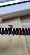
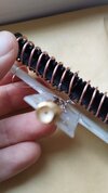
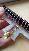
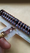
gamma-fed-nmha-4.jpggamma-fed-nmha-3.jpggamma-fed-nmha-2.jpggamma-fed-nmha-1.jpg
 
The braid is the same in every picture; its purpose being of equalizing potentials on the two CPW GND strips where two SMD parts would go - part of a lattice matching network that is not currently deployed. There is no GND plane / strip on the bottom side of PCB.

There are two 0603 zero ohm resistors: one of the GND strips has one, the other being on the central strip.

The nanoVNA got calibrated just before the SMA connector from the pictures and then used port extensions to bring Open Circuit at the two dipole feedpoint holes in the range of 5-10 kohm (both R and X)
 
Update:

Ditched the gamma matching and opted for a displaced feedpoint matching, switched over to 315 MHz (where the helix happened to resonate) took away the braid (less than 5% impedance readings difference observed), replaced one zero ohm resistor with a 91 nH inductor:

gamma-variant-fed-nmha-1.jpg

I thought I had made a lucky hit, beautiful VSWR:

gamma-variant-fed-nmha-2.jpg

And then for the real test, I have replaced the VNA with my receiver device, kept all cables and antennae placements the same; my antenna is actually a bit worse than a cheap commercial 433 MHz antenna (used at 315 MHz for this test) which has this VSWR:

commercial-dipole-433-315.jpg

For the test I have used the same transmitter running the same software and gradually departed from the receiver until it was unable to retrieve a valid signal.

The nanoVNA may be cheap, but can it be that bad ? I think not. There must be something about my method / setup...
 

Latest threads

Back
Top