Continue to Site

Welcome to our site!

Electro Tech is an online community (with over 170,000 members) who enjoy talking about and building electronic circuits, projects and gadgets. To participate you need to register. Registration is free. Click here to register now.

  • Welcome to our site! Electro Tech is an online community (with over 170,000 members) who enjoy talking about and building electronic circuits, projects and gadgets. To participate you need to register. Registration is free. Click here to register now.

Why won't my transistor work properly?

Status
Not open for further replies.

Lac

New Member
When i connect a NPN transistor with its collector to 12V and its base through a 10k resistor to a PIC to switch the transitor on, I only get 4,45V at the emitter when the transistor is turned on. How come I only get 4,45V and not full 12V?
 

Attachments

  • npn_trnasitor_problem.jpg
    npn_trnasitor_problem.jpg
    13.3 KB · Views: 905
You using the wrong configuration (emitter follower). Emitter will follow the input (base) by -0.7V

You need to put your relay or load in the collector (common emitter), of course you will have to invert the logic drive.
 

Attachments

  • transistor_problem.gif
    transistor_problem.gif
    5.6 KB · Views: 762
voltage folower

Your circuit is a voltage follower amplifier, with grounded collector. The emitter must be connected to ground via resistor (for ex. 1kOHM). On the output will appear a voltage which is approaching equal to input (base) voltage. UE=UB-UBE when the UE is the emitter voltage to the GND, UB is the base voltage to GND and UBE is the base-emitter voltage (~0,5…0,7V). Therefore your circuit knows the theory: UE=5V-0,7V=4,4V. What would you like to drive with this transistor?
 
This is when the PNP's are nice, grounding out the Base causes it to open fully and a pull-up to supply to keep it off.

Another way is to pull up the base to the input voltage and use the Pic to pull it to Gnd to turn it off.

Kent
 
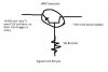
Base bias resistance is to high to drive the transistor into saturation, put a diode from the pic to the base to keep the current leaking back to a minimum. I would use it as a Com emitter.

It appears to have Vcc on the collector and GND on the emitter.

I am guessing that your pic is driving a 12 volt signal, then a drop is apparent at the resistor (6.85 volts) leaves 5.15 volts at the base, minus VBE .7v this yield at 4.45 volt dc at the emitter.

With Diode, driving a 12 volt signal, minus diode drop .7, this leave 11.3 volts at base minus VBE, which yields a 10.6 volt DC at the emitter.

To condition it to use low level signals you must use voltage dividers to drive a transistor into saturation at 12VCEcut, and figure out the resistor values needed to drive this way, acts like a clipping amp so to speak. It is better to use the collector to drive which also depends on what you are driving.
 
Status
Not open for further replies.

Latest threads

New Articles From Microcontroller Tips

Back
Top