Fluffyboii
Active Member
There is a whole argument here about using LED's in Ring modulator.
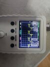
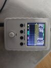
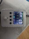
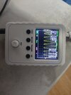
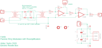
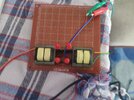
This is my own DIY ring modulator.
The question is: I don't really understand why LED's produce high volume output. They should decrease volume more because they have 1.84V voltage drop in this case while Germanium diodes have around 0.7V voltage drop. Yet Germanium diodes are quieter. Maybe there is an obvious inverse relationship here that I am not understanding. Can someone explain it.
Maybe I should use LED's as diodes more often since I have like 500 yellow LED's. I know they are crappy when used for diodes but sometimes it works enough.
Ring modulator works awesome btw. But I need to increase mic volume with an op amp and decrease square wave volume with a pot to get clean output without carrier passing through. I think for testing it gave best results when both were about 5V peak to peak. My transformers are 3400 turns of 0.07mm copper wire, 750 ohms resistance. I don't know how people calculate AC resistance or impedance for these but they say you need 10K AC resistance for 10Khz bandwidth. The transformers they use usually have 600ohm DC resistance. This ones were custom made to pass that value since I failed to find anyone selling 1:1 transformers locally.
I bought an AD633 thinking I never would get transformers. The 3 USD AD633 was obviously fake and it rapidly heats up when negative rail is connected :/
Last edited:


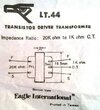
 There was a second used as an output transformer (I can't remember it's Eagle number?), which fed from the output transistors to the speaker - it was rather like a VERY old valve design. Here's a classic old circuit - the 'D' in OC81D stands for 'driver'.