Continue to Site

Welcome to our site!

Electro Tech is an online community (with over 170,000 members) who enjoy talking about and building electronic circuits, projects and gadgets. To participate you need to register. Registration is free. Click here to register now.

  • Welcome to our site! Electro Tech is an online community (with over 170,000 members) who enjoy talking about and building electronic circuits, projects and gadgets. To participate you need to register. Registration is free. Click here to register now.

WHY do these 4 transistors work good in parallel?

Status
Not open for further replies.

gary350

Well-Known Member
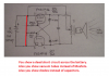
Today I came across this 12 vdc to 120 vac inverter that I built about 25 years ago. Heat sinks with 4 transistors each in parallel are industrial salvage stuff from the local scrap yard 10 cents per lbs long ago. I paid about 20¢ for these. I have a 120vac to 24vac CT transformer connected with 24v as the primary. 12v car battery produced 120vac. It will light up a 100 watt light bulb. At the campground it would light up several smaller 7w lights and strings of Christmas tree lights. Only datasheet information I find on the 7018 transistors is 1500v 5a. This is not very important anymore with $25 inverters that work good these days.

I tried to build this same circuit with 2N3055 transistors but transistors will not work in parallel. I tried nichrome wire to connect emitters in parallel but it

never worked.

Why do the 7018 transistors work in parallel but other transistors won't?

100_2770.JPG


100_2772.JPG


100_2765.JPG


100_2775.JPG
 
Last edited:
You can't put BJTs in parallel because they conduct better (lower C-E voltage drop) the hotter they get. Due to manufacturing variations, no BJT is identical, so the BJT that is the most efficient carries a bit more of the load current than the others which makes it hotter, which reduces it's C-E voltage drop which makes it carry even more the total load current which makes it even hotter until it's the only one carrying all the current and none of the others are and it fries. If you do put them in parallel, you need to put a so-called current balancing resistor in series with every BJT to prevent this from happening.

MOSFETs conduct worse (higher D-S voltage drop) when they get hotter, so as one gets hotter, it less of the total load current flows through it and instead flows through the other MOSFETs which heats those up so they don't conduct as well and a balance is maintained amongst all the MOSFETs.
 
Last edited:
Why do the 7018 transistors work in parallel but other transistors won't?
Could be that they are well enough matched that one doesn't hog too much of the total current as to damage it.
 
You can't put BJTs in parallel because they conduct better (lower C-E voltage drop) the hotter they get. Due to manufacturing variations, no BJT is identical, so the BJT that is the most efficient carries a bit more of the load current than the others which makes it hotter, which reduces it's C-E voltage drop which makes it carry even more the total load current which makes it even hotter until it's the only one carrying all the current and none of the others are and it fries. If you do put them in parallel, you need to put a so-called current balancing resistor in series with every BJT to prevent this from happening.

MOSFETs conduct worse (higher D-S voltage drop) when they get hotter, so as one gets hotter, it less of the total load current flows through it and instead flows through the other MOSFETs which heats those up so they don't conduct as well and a balance is maintained amongst all the MOSFETs.


I was told small resistor like nichrome wire connecting transistors in parallel will work but it did not work on 2N3055.
 
Last edited:
That horrible old schematic is the same as the one on Aaron Cake's website that does not work.
Its capacitor polarities were backwards and it used only a single pair of 2N3055 transistors.

Its problem is that each capacitor charges to about +23V then discharges into the base of the other transistor. But most silicon transistors including the old 2N3055 transistor are destroyed if their reverse emitter-base voltage is more than 7V. It is called avalanche breakdown.

The 7018 transistor is so old that its datasheet is not available. It was a high voltage transistor used in an old TV. Maybe four in parallel are not zapped in that circuit.

The inverter produces a squarewave output that will not power many modern electronic products that rely on the 170V peak voltage of a 120VAC sinewave.

I developed a fix for the problem:
 

Attachments

  • inverter again.png
    inverter again.png
    435.6 KB · Views: 171
Its problem is that each capacitor charges to about +23V then discharges into the base of the other transistor. But most silicon transistors including the old
2N3055 transistor are destroyed if their reverse emitter-base voltage is more than 7V. It is called avalanche breakdown.

I don't know if I've mentioned it before, but years back when I was at college we were given a project to do, it had been kicking about for years, but we were the first year that they thought might be able to do it.

It was just a block diagram, for a very simple 'slot machine'. It used three 7 segment filament displays (it long predated LED's), and basically the device rotated the three horizontal lines on the displays, and you had to press a button under each display to stop it, and the game was to stop all three on the same horizontal line. The requirements were pretty well fixed, no IC's (even though they were available by then), built on plain matrix board with all components and wiring on the top (so all workings were visible under the perspex cover it was finished with).

So basically (from what I remember) it was three astables, three ring of three counters, three bistables (for the stop buttons), three drivers for the displays, and logic gates to light win or lose bulbs. Each section of the circuit was built on it's own matrix board, and wired together, and originally we were split into two teams each making one - with sections of each team allocated particular boards.

Anyway, after a while they decided to drop to a single team, in order to get it ready for an open day which was coming up.

Now - the reason I'm mentioning this, my teams sections were all done, but the other team were struggling getting the astables working, and had a huge pile of blown transistors. The astables were running off 9V, and this almost instantly blew the transistors every time you turned it ON - I pointed this out to the leader of the other team, and showed him how to fit protection diodes to prevent it (as in AG's example above), but he refused to do so, and carried on blowing transistors. Eventually he managed to find some transistors which actually survived the abuse, and the project was completed and worked perfectly.
 
That horrible old schematic is the same as the one on Aaron Cake's website that does not work.
Its capacitor polarities were backwards and it used only a single pair of 2N3055 transistors.

Its problem is that each capacitor charges to about +23V then discharges into the base of the other transistor. But most silicon transistors including the old 2N3055 transistor are destroyed if their reverse emitter-base voltage is more than 7V. It is called avalanche breakdown.

The 7018 transistor is so old that its datasheet is not available. It was a high voltage transistor used in an old TV. Maybe four in parallel are not zapped in that circuit.

The inverter produces a squarewave output that will not power many modern electronic products that rely on the 170V peak voltage of a 120VAC sinewave.

I developed a fix for the problem:

The improved circuit drawing is interesting. If I still had a 24v CT transformer I will build this just to see how it compares to the other circuit. It use to power a 100w light bulb. The only diodes that I have are 1N4007 how important is it to have 1N4001 and 1N4002 in this circuit. Not likely I have any 68uf caps or 33uf to connect in parallel but I probably have 47uf an 22uf = 69uf. I will make notes on the circuit drawing. I have an idea that might be FUN, I have a 1 to 1 ratio transformer rated about 200w and several 100w speakers, if I change the 68uf cap to get higher Hz it will make a great 100w horn. LOL I use to have 300 lbs of old transformers, wish I still had them. I'm not sure what a good KHz is for a horn maybe 2K or 3K.

No way to know what this 4 transistor thing was originally used for I rescued it from the scrap yard. One 2N3055 will do the same thing as these 4 transistors.
 
The datasheet for the 1N4001 to 1N4007 diodes shows that any of them can conduct 1A continuously and can conduct 30A brief pulses. The diode current in this circuit is only mA. The max allowed reverse voltage for a 1N4001 is 50V but it gets only 24V in this circuit and a 1N4007 can be used instead because its max allowed reverse voltage is 1000V.

The circuit will not work with a 1:1 transformer, the center tap is important. You can make the similar multivibrator circuit you used to blink LEDs to make a buzzer sound fed to an amplifier and a speaker.

I am talking about primary with CT ratio is 1 to 1 with 12v on both windings. I can wind my own in the lathe in 30 minutes. I already have coil forms built to wind my own transformer coils. I can wind any ratio I want not sure what is best voltage for the speaker?

100_2776.JPG
 
Last edited:
Ohm's law calculates that with only 12VAC in an 8 ohms speaker, the power is only (12V squared)/8 ohms= 18W. But if the transformer produces 24VAC then the power in the 8 ohm speaker will be (24V squared)/8 ohms= 72W. A mains transformer works poorly at audio frequencies.

But the circuit does not have enough base current (12V - 0.8V)/180 ohms= 62mA for the transistors to saturate so each transistor produces 12V at 0.62A= 7.4W then the output power in the speaker will be only 14.8W.
Like I said, it is horrible lousy old circuit.
 
Are you doing math for 2N3055 transistors?

I don't have to use this horrible circuit, I can use mosfet circuit to power a speaker.
 
Last edited:
Sanken uses the traditional 2SA, B, C, and D for the part numbers of their bipolar transistors. STA is the prefix they use for "array" devices, which means there's more than just a transistor in that case. it could be a transistor and a low value (between 0.1 and 0.47 ohm) resistor right on the silicon. there are no data sheets for the STA part, so it's probably an OEM part. the only bipolar transistors that can be paralleled successfully (without emitter resistors) are germanium. i've seen some old amplifier schematics showing Ge transistors paralleled.
 
Dose any one recognize the maker? I don't think it is Sanken. I have some Sanken parts and can go check.
1552321115894.png

This is what a Sanken part looks like. "SK"
---Edited
1552331202557.png

---Edited
Found then in China. They don't know what they are. "STC"
1552331850685.png
 
Last edited:
the only bipolar transistors that can be paralleled successfully (without emitter resistors) are germanium. i've seen some old amplifier schematics showing Ge transistors paralleled.

I can't say I've ever heard that?, or seen any paralleled germanium devices without emitter resistors, and I was under the impression that germanium transistors were more prone to thermal runaway than silicon ones?.

However, it makes sense that the STA transistors could have suitable emitter resistors built-in.
 
Status
Not open for further replies.

Latest threads

New Articles From Microcontroller Tips

Back
Top