Electro Tech is an online community (with over 170,000 members) who enjoy talking about and building electronic circuits, projects and gadgets. To participate you need to register. Registration is free. Click here to register now.
Welcome to our site! Electro Tech is an online community (with over 170,000 members) who enjoy talking about and building electronic circuits, projects and gadgets. To participate you need to register. Registration is free. Click here to register now.
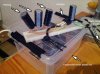
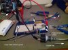
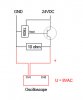
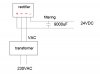
Please post a detailed schematic instead of the photo of tangled wires.
I think you have the pins of the full-wave rectifier bridge mixed up.
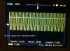
Why is your 'scope not sync'd?
Are you referring to that the waveform flickered across the screen? I don't know, I just started out with electronics. But when I did a single capture, it was a sine wave of circa 8VAC between transistor emitter and gnd.
I question of the scope ground is working. I can see the wire but some times the copper wire inside the insulation is broken.
Trying measuring the output of the 5 volt regulator. Does it also have 8VAC on it?
Because your 'circuit' is complete nonsense - why have you left out all the required parts and connected it completely wrongly?. It will be unstable and oscillating.
Because your 'circuit' is complete nonsense - why have you left out all the required parts and connected it completely wrongly?. It will be unstable and oscillating.
I have filter caps on the in and output of the 7805. I expected to see circa 4.35V at transistor emitter. Can you help explain why this is not the case? M
Yes, the regulator is oscillating at a high frequency because it is missing the important output capacitor recommended on its datasheet. It might also need an input capacitor if the main filter capacitor is not very close by.
Then it is not the 0.1uF high frequency capacitor shown on the datasheet. A 10uf electrolytic capacitor has a high impedance at high frequencies due to its inductance.
The output from the regulator isn't oscillating at all.
The meter measures between circa 5-7VDC and 45-60VAC. The scope measures RMS 8. The waveform is a sine wave. The load is a light-bulb. Before I connect the lead to the collector of the npn transistor, i only get 5V from 7805 via the base. Once i connect the main current to the collector, I get this AC current. :/ If I ditch the transistor and the regulator, and hook the load straight to the 24VDC rail, i get no only DC current.
I think the voltage will be different if you touch one of the wires.
What does the scope see across the load? (with the transistor disconnected)
I am trying to find out if we are picking up a radio station on the long wires.
This site uses cookies to help personalise content, tailor your experience and to keep you logged in if you register.
By continuing to use this site, you are consenting to our use of cookies.

") M
M