after i go through some data sheet for LM350 adjustable voltage regulator
LM350T pdf, LM350T description, LM350T datasheets, LM350T view ::: ALLDATASHEET :::
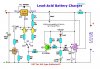
i don not understand why this circuit need put LM334, 3-Terminal Adjustable Current Source, anyone can help me?
LM350T pdf, LM350T description, LM350T datasheets, LM350T view ::: ALLDATASHEET :::
i don not understand why this circuit need put LM334, 3-Terminal Adjustable Current Source, anyone can help me?