Electro Tech is an online community (with over 170,000 members) who enjoy talking about and building electronic circuits, projects and gadgets. To participate you need to register. Registration is free. Click here to register now.
Welcome to our site! Electro Tech is an online community (with over 170,000 members) who enjoy talking about and building electronic circuits, projects and gadgets. To participate you need to register. Registration is free. Click here to register now.
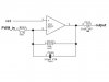
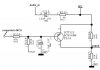
First one's an integrator, works like a low-pass filter, but one of the inputs is connected to Vcc, which is a mistake. The second one makes even less sense, that Audio_in signal should be killed off at the +2V junction and never make it to the transistor.
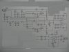
The first circuit is a low pass filter, -3dB point @ 24kHz. The second looks like an unmute type circuit - apply a low voltage to the base of the transistor and the current passed increases, thus increasing the volume. The full schematic you posted was pretty much unreadable. It looks like it just buffers the left & right channels, with weak mute function and a tone injection into both ears (e.g. for beep indications)
The output from the buffer/gain-control section feeds into a headphone amp (LM4881). I might guess the circuit's allows the audio level to be reduced while it plays tones - e.g. to notify you that the phone's ringing while you're listening to music.
The -3dB point refers to where a filter's cut off frequency. It's calculated for that little snippet of circuit from the value of the resistor and capacitor in the negative feedback path. the 24kHz is calcuated using Fc = 1/(2*pi*R*C). google filters for more info
This site uses cookies to help personalise content, tailor your experience and to keep you logged in if you register.
By continuing to use this site, you are consenting to our use of cookies.