Continue to Site

Welcome to our site!

Electro Tech is an online community (with over 170,000 members) who enjoy talking about and building electronic circuits, projects and gadgets. To participate you need to register. Registration is free. Click here to register now.

  • Welcome to our site! Electro Tech is an online community (with over 170,000 members) who enjoy talking about and building electronic circuits, projects and gadgets. To participate you need to register. Registration is free. Click here to register now.

Whistle Switch/Clap Switch circuit

Status
Not open for further replies.

Sbuda

New Member
Hi people.

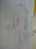
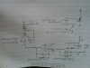
Can you help me with building a circuit with an LED that turns ON when you whistle, and OFF when you whistle again. It's a school project. It's should have the high pass and low pass filters.

I am supposed to measure the frequency on the microphone and an amplitude by whistling, then choose choose the capacitor values for the filters and calculate the gain and the resistor values.

For now I have measured the the frequency to be 2,016 kHz and amplitude to be 208 mV.

I now have no idea how to continue. Please help.
 

Attachments

  • block diagram.jpg
    block diagram.jpg
    299.7 KB · Views: 277
  • circuit diagram.jpg
    circuit diagram.jpg
    329.3 KB · Views: 286
Please note: I have uploaded the block diagram and the circuit diagram as given the teacher, but i will accept any other way as long as it has got the filters.
 
Looks good so far, although the images you posted are upside down and sideways. 2 kHz is awfully high for a human whistle; are you sure about that measurement?

What have you been taught about single-pole filters, corner frequencies, etc?

ak
 
The filters are so simple (first order) that they are almost useless. You need third order filters or better.
Usually the output level from a microphone is very low and is amplified before being filtered.
Your "precision" rectifier is not precision because it has a diode voltage drop. The rectifier diode must be inside the negative feedback loop of the opamp to cancel the diode's voltage drop.
 
Hello Sbuda,
but i will accept any other way as long as it has got the filters.
The method is good just as an input, can you use PLL IC 565 and a filter for around 1Khz for the same? As AnalogKid said, 2Khz is a bit high for human whistle.

Regards,
Manu
 
Looks good so far, although the images you posted are upside down and sideways. 2 kHz is awfully high for a human whistle; are you sure about that measurement?

What have you been taught about single-pole filters, corner frequencies, etc?

ak
i was too close to the mic when i whistled, but i will try to redo measurements again with the lower frequency.... about the single pole filters and corner frequencies i think it's my first time hearing about those.
 
Last edited:
The tone controls on your stereo are single pole filters. They reduce the high and low frequencies a little, they do not remove them. The simple "whistle" detector will also detect a dog barking or an airplane or a motorcycle.
 
2kHz is too high for a human to whistle? I am a human and I can easily whistle 2kHz or 1kHz or 500Hz and many more frequencies.
 
The tone controls on your stereo are single pole filters. They reduce the high and low frequencies a little, they do not remove them. The simple "whistle" detector will also detect a dog barking or an airplane or a motorcycle.
how to make it?
 
The simple useless filters are 1st-order. You can use 2nd-order or 3rd-order Sallen and Key highpass and lowpass filters. If your frequency is fairly accurate then you can us a Multiple Feedback Bandpass filter. Look at them in Google.
 
Status
Not open for further replies.

New Articles From Microcontroller Tips

Back
Top