Continue to Site

Welcome to our site!

Electro Tech is an online community (with over 170,000 members) who enjoy talking about and building electronic circuits, projects and gadgets. To participate you need to register. Registration is free. Click here to register now.

  • Welcome to our site! Electro Tech is an online community (with over 170,000 members) who enjoy talking about and building electronic circuits, projects and gadgets. To participate you need to register. Registration is free. Click here to register now.

Which wire goes where? FAN

Status
Not open for further replies.

camerart

Well-Known Member
Hi, (Uk)
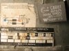
I have a fan from a paper drier, which has 4x wires Brown, Blue, Black and green.
Here is a photo of the connection sticker, with a capacitor I bought. Can anyone tell me which wires go where please?
I tried Brown, Blue and Green in a 3 pin plug, the motor hums and if spun starts up, but gets hot.
Camerart.
 

Attachments

  • FAN connections.jpg
    FAN connections.jpg
    196.6 KB · Views: 138
Measure the resistance between each of the 4 wires.
One pair should be the start winding the other the run.
Max.
 
Is the green wire a GND? i.e. go to the frame of the motor?
If so measure the resistance between the remaining conductors.
Max.
 
The nameplate data shows a 4.0 uF capacitor. I see what looks to be a blue dot, black dot and an orange dot? Would this be a reversable fan motor?

Ron
 
This is why I asked for the winding resistance, if both the same then it would be a common PSC motor and either winding would work, just opposite direction.
Max.
 
A gesture, until more of what it is and does can be determined.

umm, that looks to be a 2 speed single phase fan description. L Load, N Neutral, Z... ? The capacitor looks to go to the neutral and the Z orange.

Also states minimum capacitor voltage would be 400V. Inductive system.

A centrifugal fan?
 
Hi M,
Green = GND/Body of motor.

Blue Brown 68 Ohm
Blue Black 58 Ohm
Black Brown 123 Ohm.
C.

Then I would consider that a PSC motor, if you Google the same, you will get all kinds of post showing the connections, with a PSC if you happen to hook up the opposite winding it will just run in reverse, if so just swap the windings over.
Max.
 
Hi All,
It's working!
Yes, it is reversible.
I can now understand the diagram at #1. The two black squares are the windings, and next to it the switch. The orange/red is Brown.
I dug the blower out to blow away the White fly from my long gone tomatoes, I'm ready for 'em next year:D
Thanks.
C.
 
Status
Not open for further replies.

Latest threads

New Articles From Microcontroller Tips

Back
Top