Continue to Site

Welcome to our site!

Electro Tech is an online community (with over 170,000 members) who enjoy talking about and building electronic circuits, projects and gadgets. To participate you need to register. Registration is free. Click here to register now.

  • Welcome to our site! Electro Tech is an online community (with over 170,000 members) who enjoy talking about and building electronic circuits, projects and gadgets. To participate you need to register. Registration is free. Click here to register now.

Where to find a replacement circuit board?

Status
Not open for further replies.

Mark563

New Member
Where to find a replacement circuit board?

Hello, people,
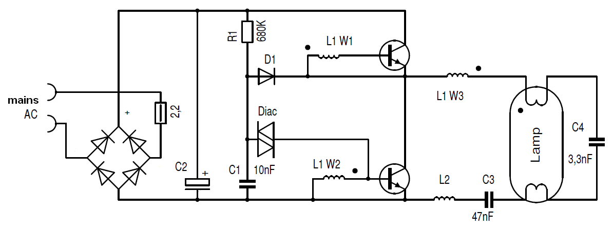
A friend gave me this fluorescent magnifying desk lamp, 'cause it wasn't working.
Markings on the unit include: E78751, ULM#LTS60001, and Issue BK-68.395.
One end of the bulb was black, so I bought a new bulb. Still, it won't work.
So, I took it apart, and found that part of the circuit board looks dark / burnt.
Anybody know where I can get a new PC Board for this?
**broken link removed**
And another question...
My understanding is that Fluorescent bulbs require a "starter" of some kind.
Is that it, that's shown in the picture? If not, then what is that part for?

Thanks for your time.
Mark563
 
Last edited by a moderator:
Darn,... why are my pictures not shown?
I tried to insert links to individual pics from Dropbox.

Aha ! I think I figured it out...
**broken link removed**
 
Last edited by a moderator:
Welcome to ETO

Upload pictures to ETO
 
Thanks for the "Welcome", Mr. Inquisitive.

I tried uploading, via the "upload a file" link.
I navigated to the folder on my computer where the JPG files are, and ETO said there are no files in that folder.

And, an additional bit of information that might be useful...
The old bulb says "T4 12W 6400K". The new bulb says "FCL/T4 11W".
I'm thinking... replace that entire PC board with something else, even if it's not the same thing.
Any similarly functioning board that will power an 11Watt or 12Watt bulb?

Thanks, people.
 
I tried uploading, via the "upload a file" link.
I navigated to the folder on my computer where the JPG files are, and ETO said there are no files in that folder.
Hy Mark,

The problem that you describe with uploading files on ETO is normally due to a setting in your browser. Many of us have had the same problem.

I only know about Firefox:

Go to: Tools > Add-ons > Plugins

Then left click on 'Shockwave'

Click on 'more' and uncheck 'Enable Adobe Flash protected mode'

Hope this fixes your uploading problem.:)

spec
 
On mine (Chinese origin) I had it for about 1-2yrs and it started to act up sometimes work, some not, or it would all of a sudden go off.
Ordered a new lamp and OK for a while then act up again.
Decided to check it out and ultimately found a bad AC connection where the cord was terminated by a couple of screw nuts, found both live and neutral connections were intermittent, fixed it and not problem ever since.
You may be as lucky!!
Max.
 
My understanding is that Fluorescent bulbs require a "starter" of some kind.
Is that it, that's shown in the picture? If not, then what is that part for?
Issue 3 of 2016_08_15

Hy again Mark,

There are a few different types of fluorescent tubes (FTs). The tube in your lamp is likely to be a a Compact Fluorescent Lamp (CFL) that are widely used in room lighting or a Cold Cathode Fluorescent Lamp (CCFL) as used to back illuminate LCD displays on monitors and TVs.
CONSTRUCTION of FTs
(1) FTs comprise a tube filled with gas, typically mercury vapor, and a traces of other gasses to promote easier starting.
(2) Electrodes are fitted to each end of the tube. CFLs have a heater at each end and thus have two terminals at each end but CCFLs have no heaters and thus only have two terminals.
(3) The inside of the glass tube is coated with a fluorescent coating which emits light when the coating is struck by ultra violet light.
OPERATION of FTs
(1) A high AC voltage (50HZ to 50KHz) of between 400V and 2KV peak is connected between the two electrodes. This causes the gas to ionize and generate ultra violet light.
(2) Once ionization has started, and the gas has heated up, ionization continues at a lower voltage, typically 400V peak.
(3) The ionizing gas gives off ultraviolet light, but not white light, which causes the florescent coating on the inside of the tube to emit white light. The florescent coating comprises a mixture of materials formulated to emit white light.
(4) CFLs need their two cathodes to be heated before they will start but, once they have started, the heaters can be turned off as the ionization of the gas provides sufficient heat to continue operation. On the other hand, CCFLs, do not have heaters, and rely on a sufficiently high voltage across their terminals to initiate ionization.
DRIVING FTs
(1) Small FTs, like in your table magnifier lamp, are normally driven by an inverter.
(3) The inverter operates from DC, in your case rectified 110V 60Hz, which would give a 150V DC supply line.
(4) The inverter normally has built-in protection, so that if it is overloaded by a high current it will shut down or blow a fuse.
FAULT FINDING (WARNING: DANGEROUS VOLTAGES ARE PRESENT ON ALL PARTS OF THE FLORESCENT TUBE CIRCUIT. ON NO ACCOUNT TOUCH ANY PARTS OF THE CIRCUIT OR FLORESCENT TUBE WHILE THE UNIT IS PLUGGED INTO THE MAINS SOCKET)
Although your control board is discolored, it is not charred and is likely to be still operative.
(1) The first thing is to check all joints for continuity. You will need to remove the insulation over the 'starter' to do this.
(2) Check all wires for continuity. It is common for the wire near to the connection to the FT to oxidize, due to the FT heat, and go open circuit.
(3) Check all joints on the Printed Circuit Board (PCB) for continuity, especially in the area that is discolored. Solder joints can appear to be OK but are in fact crystallized/oxidized and thus a high resistance. It would be best to reflow the joints on the PCB with new solder, especially in the discolored area.
(4) The next step would be to heat the FT to about 70 Deg C with a hairdryer (make sure you heat all parts of the FT) and see if the FT starts up.
(5) Further fault finding is possible which we will be able to define for you if necessary.

spec
 
Last edited:
Thanks for the replies,people.

Max... no such luck. The PC board gets 120VAC just fine.

Wow, Spec,... information overload ! :) Very cool!
You think the board might still be operational? Great!...

A voltmeter says the board IS getting 120VAC.
At the other end of the board, the two wires go to the lamp show no voltage. (Should that be AC or DC there?)

I Googled Capacitor images... nothing like that "Starter" thing that I asked about.

Darn... I did the "Disable Adobe Flash" as you suggested, Spec, and then restarted Firefox... same result.
Please view the Dropbox pictures...
**broken link removed**
So, on the PCB, which part is the Capacitor? #1 or #2 or #3?

The "CCFL"... that's the bulb, Correct? And if I apply a hairdryer, it will light up? Wow. Never knew that.

You mentioned the wires near the connection to the CCFL...
Are you referring to up near the CCFL, or on the PCB?

Oh, yeah,... further explanation Is necessary. :confused:

Mark563
 
Last edited by a moderator:
Starter.jpg


[Mod inserted photo]
 
Last edited by a moderator:
Thanks for the replies,people.

Max... no such luck. The PC board gets 120VAC just fine.

Wow, Spec,... information overload ! :) Very cool!
You think the board might still be operational? Great!...

A voltmeter says the board IS getting 120VAC.
At the other end of the board, the two wires go to the lamp show no voltage. (Should that be AC or DC there?)

So, on the PCB, which part is the Capacitor? #1 or #2 or #3?

Mark563
Capture #994 - 'IMG_20160813_121455_654 6 noted _'.jpg

1 and 2 are caps 3 is an inducter/coil .

My red circle is most likely hiding a fuse or fusible low ohm resistor within.
If it's blown, then either green circled diodes or blue circled transistor is shorted /open.

Do not measure voltage at bulb terminals, or the output... too high for your meter.
Since it is not working there is no voltage and your meter is still safe.

This board has high voltage and line voltage that can bite you. be very careful.

Best to use your resistance and diode check settings to trouble shoot without power applied .
 
Issue 3 of 2016_08_15

Darn... I did the "Disable Adobe Flash" as you suggested, Spec, and then restarted Firefox... same result.
Hmm, that is a pain- it normally fixes that problem.
You think the board might still be operational?
I suspect the board may be OK, or it may have a repairable fault. The only component that would not be available is the inductor (large item at lower right on your image).
A voltmeter says the board IS getting 120VAC.
That is good
At the other end of the board, the two wires go to the lamp show no voltage. (Should that be AC or DC there?)
Yes, I would expect 400V peak (282 RMS) to 1000V peak (707V RMS) across the two wires going to the FT; a meter set to AC input would read RMS but as the frequency of the AC is liable to be high the meter may be inaccurate or possibly read very little. There is no voltage present either because the main PCB circuit detects a fault with the wiring say, or because the main PCB has a fault. Beware of connecting your meter directly to any parts of the circuit or the meter may be damaged, as pfofit warns.
I Googled Capacitor images... nothing like that "Starter" thing that I asked about.
No, I would not expect to get any hits on 'starter'. If it is a capacitor, as I suspect, it will be a standard high voltage capacitor, not specifically described as a starter.
Please view the Dropbox pictures...
**broken link removed**So, on the PCB, which part is the Capacitor? #1 or #2 or #3?
I suspect that what you describe as the 'starter' is a heater capacitor (CFL) or current limiting capacitor (CCFL)
The "CCFL"... that's the bulb, Correct? And if I apply a hairdryer, it will light up? Wow. Never knew that.
As florescent tubes age they take more and more voltage between their electrodes to start the ionization. By heating an FT you make the gas inside the FT more active so that it will ionize at a lower voltage. But as there is no voltage from the main PCB, your FT will not start with heating.
You mentioned the wires near the connection to the CCFL... Are you referring to up near the CCFL, or on the PCB?
I was referring to the connections physically to the FT. This is a common source of problems with FTs due to the high temperature of the FT when it is running and also due to the nature of the connecting wire which is designed for high voltage and tends to corrode easily.

spec
 
Last edited by a moderator:
After a closer examination I am wondering if your tube is a florescent tube with heaters. Does the tube have a total of four contact pins?

If that is the case, the 'starter' may still be a capacitor that provides the current to heat up the two tube cathode heater elements and allow the florescent tube to start.

spec
 
Last edited:
Hy Mark,

Assuming that your tube has heaters, a typical small tube controller schematic is shown below.

The 'starter' on your desk lamp could be C4.

L1, an inductor, is the large component lower right on the image in pfofit's post #10. A multi winding (W1, W2, W3) inductor physically, and on a schematic, looks like a transformer and while an inductor and transformer are closely related their function is quite different.

https://en.wikipedia.org/wiki/Fluorescent_lamp

spec

Fluorescent_Lamp_Inverter.png
 
Last edited:
View attachment 100811
1 and 2 are caps 3 is an inductor/coil.
Hi pfofit,

There should be a bridge rectifier in the circuit. I suspect that #1 is the bridge rectifier: what do you think?

I suspect that #2 is the reservoir capacitor.

The fuse that you highlight is included in the schematic of post #13.

spec
 
Last edited:
Another fluorescent tube controller schematic below.

**broken link removed**

spec
**broken link removed**
 
Hy Mark,

Just in case, a DIAC is open circuit until the voltage across its two terminals reaches a certain voltage, typically 30V, when it goes to a low resistance until the current through the DIAC drops below a certain value (holding current) when the DIAC returns to an open circuit. DIACS are used in light dimmers, motor speed controllers, and oscillators in general. https://en.wikipedia.org/wiki/DIAC

I suspect that the component circled in cyan on the image in pfofit's post #10 is a DIAC rather than a simple diode.

spec
 
Last edited:
Post #7 and #11 have been rewritten to cover both Compact Fluorescent Lamps (CFLs), with heaters, and Cold Cathode Florescent Lamps (CCFLs), with no heaters.

spec
 
Last edited:
Interesting site: http://www.pavouk.org/hw/lamp/en_index.html

Extract:
Failures
Common failure is broken [short circuit or open circuit] capacitor C3. it is possible mainly at [with] cheap lamps, where are used cheaper components for lower voltage. Whet [when] the pipe [tube] doesn't lights up on time, there are risk of destroying transistors Q1 and Q2 and next resistors R1, R2, R3 and R5. When lamp starts, changer is very overloaded and transistors usually doesn't survive longer temperature overloading. When the pipe serve out [tube fails], electronics is usually destroyed too. When the pipe [tube] is old, there can be overburned one of [open circuit] filaments and lamp doesn't lights up anymore. Electronics usually survives. Sometimes can be pipe broken [the tube can be physically damaged] due to internal tension and temperature difference. Most frequently lamp fails, when power on.


Repair of electronics
Repair of electronics usually means change of capacitor C3 if he is brobek [broken]. When burns [blows the] fuse, probably will be damaged transistors Q1, Q2 and resistors R1, R2, R3, R5. You can replace fuse with resistor 0R5. Failures can be multiplied. For example, when is shorted capacitor there can be thermally overloaded transistors and will be destroyed. Best transistors for replacing of original types are MJE13003, but it is not easy to find them. I replaced them with BD129, but they are not available now. There exists other variants like a 2SC2611, 2SC2482, BD128, BD127, but I am not sure if they will be long-life. Original transistors are not available on our market. If doesn't matter size of case TO220, it's possible to use transistors MJE13007.

Mark, in theory, you should be able to use the entire circuit board from a CFL, which are available quite cheaply. But perhaps the best approach would be to repair your existing board with components salvaged from a CFL board.


I have a box full of old CFL bases which I use for experiments/source of components.

spec
 
Last edited:
Hi pfofit,

There should be a bridge rectifier in the circuit. I suspect that #1 is the bridge rectifier: what do you think?

I suspect that #2 is the reservoir capacitor.

The fuse that you highlight is included in the schematic of post #13.
spec

Maybe #2 is a bridge, hard to tell from the pic as the top is out of focus and not sure why they heat shrinked it but appears to have a k type vent.
I was thinking the diode in the upper left near the line wire is half of a voltage doubler using 2 caps.
Like so from a reversed drawing from many moons ago.
sylvania comact schema.JPG


I have a box full of old CFL bases which I use for experiments/source of components. spec
Ha ha, great minds think alike or "you can't throw anything away either", huh. :)

edited: just noticed a couple more black diodes hiding to right of the green cap and to th eleft of the right side transitor.
Can the OP produce a larger more in focus pics from a couple angles.
 
Last edited:
Ha ha, great minds think alike or "you can't throw anything away either", huh. :)
:D yes, it is a disease and I don't know where it comes from. Apart from student, days I have never wanted for anything.

My misus said that if I brought any more junk home she would leave, but she never did!

spec
 
Status
Not open for further replies.

Latest threads

New Articles From Microcontroller Tips

Back
Top