Continue to Site

Welcome to our site!

Electro Tech is an online community (with over 170,000 members) who enjoy talking about and building electronic circuits, projects and gadgets. To participate you need to register. Registration is free. Click here to register now.

  • Welcome to our site! Electro Tech is an online community (with over 170,000 members) who enjoy talking about and building electronic circuits, projects and gadgets. To participate you need to register. Registration is free. Click here to register now.

wheel mouse

Status
Not open for further replies.

samarsingla

New Member
hi
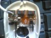
opened up an old wheel mouse. a wheel with perforations is revolving and a photo-transistor, led pair sense the gaps and closed portions of the wheels. how does it get to know in what direction the mouse is moving? i mean the direction of spinning of the wheel.
please anybody who knows tell me.
thanx.
 
It is probably a quadrature encoder. Each LED has a detector across from it and the wheel spins in the middle. The gaps in the wheel cause the detector to see flashes of light, either dark or light (0 or 1 is what is seen digitally)

Notice you have an LED pair? That means you have two light-sensors, one to go with each LED. Each emitter/detector pairs is positioned 90 degrees out of phase. This means that if you take the current value of each detector (light/dark or 1/0 in digital) and compare it with the pair of values from the last reading you can tell the direction it is going because the values are unique.

For example for a motor (or wheel) spinning:
=================================
Constantly spinning clockwise
Detector A: 101010101010101010
Detector B: 010101010101010101

Therefore motor is spinning clockwise if:
A/B = 1/0 previously and is now 0/1 OR
A/B = 0/1 previously and is now 1/0
================================
Constantly going counter clock-wise:
Detector A: 10101010101010101010
Detector B: 10101010101010101010
Therefore the motor is spinning counterclockwise if:
A/B = 0/0 previously and is now 1/1 OR
A/B = 1/1 previously and is now 0/0

I am pretty sure these values are not the combination an encoder really outputs, it is just an illustrative example to sort of describe how it is interpreted.

You can determine speed by counting how many flashes occur per second or minute or whatever.
 
Last edited:
You aren't looking at the scroll wheel right? I only opened up ball mice a few times a long time ago before I knew anything about them. The only slotted wheel in my optic mouse now is the one for the scroll wheel.
 
Last edited:
no i didnt. its still working only the circuit and wheel. thats why i am surprised. i tried passing small wires though the gap, still it senses the direction correctly. i am amazed...
 
If it was a quad encoder the wire might not do anything noticeable by you since you would have to hold it so perfectly to block any light from getting through the slot while moving the mouse.

Maybe you can get more answers here:
https://computer.howstuffworks.com/mouse2.htm
 
Last edited:
the mouse i am seeing is actually having only two buttons, no scroll wheel. it is a ball mouse. the wheels are for encoders only.
 
The HowStuffWorks article says there should be two LEDs per wheel. Makes sense for what I said, but not for what you have...
 
How many light detectors are there? Because there HAS to be four if it's a quad encoder (I can't think of it being anything else the way you described it). It might be that instead of using two LEDs per wheel, one LED is used from behind a barrier with two pinholes that are positioned 90 degrees out of phase, to simulate two LEDs thare are 90 degrees out of phase.
 
Last edited:
here's the pic. only one led, no barrier also. what do you mean by 90 degree out of phase. you mean ac supply is being given to leds?
 

Attachments

  • TMPAAAEC.jpg
    TMPAAAEC.jpg
    258.6 KB · Views: 215
[ORIGINAL MESSAGE BEFORE CORRECTON]
No, it has to do with the sine wave you can draw to represent the state of the LED/detectors. The sine wave of each pair is 90 degrees out of phase.

I can't see stuff in your picture too clearly, except that does only seem to be one LED per wheel.

Wait until morning on my side of the world...maybe someone else knows.
No, it has to do with the square wave you can draw to represent the state of the LED/detectors. The square wave of each pair is 90 degrees out of phase.

I can't see stuff in your picture too clearly, except that does only seem to be one LED per wheel.

Wait until morning on my side of the world...maybe someone else knows.
 
Last edited:
Sorry, I should have said square wave. When I say phase shift I start thinking sinusoid.

Let me restate it again:The two square waves outputted by the detectors are phase shifted to by 90 degrees. (Shifted by 25% of their period). This causes the 1s and 0s to be paired up in such a way so you can determine direction.

I will correct it in my previous posts.
 
Last edited:
you saw the pic. did you understand how it works. the receiver is a phototransistor(thee terminals) and there is only one led....
 
Yeah...sorry I still don't get that. The only way I can see a single LED/emitter per wheel is an absolute encoder wheel where each segment is unique. But you say yours is slotted the same way all around.
 
Last edited:
samarsingla said:
but there is only one led receiver pair per wheel..

We've been through this on a previous thread!, it has TWO sensors per wheel, although many modern ones have them built in a single encapsulation so it's not obvious.
 
could you please elaborate on that a bit more. do you mean two leds and two photodiodes or something. please explain or giv me some link to follow. thanx
 
Status
Not open for further replies.

Latest threads

New Articles From Microcontroller Tips

Back
Top