Continue to Site

Welcome to our site!

Electro Tech is an online community (with over 170,000 members) who enjoy talking about and building electronic circuits, projects and gadgets. To participate you need to register. Registration is free. Click here to register now.

  • Welcome to our site! Electro Tech is an online community (with over 170,000 members) who enjoy talking about and building electronic circuits, projects and gadgets. To participate you need to register. Registration is free. Click here to register now.

Whats wrong with this LTspice circuit?

Status
Not open for further replies.

antknee

New Member
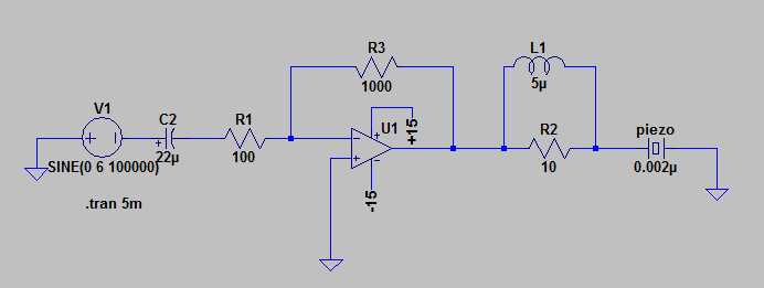
I discovered LTspice yesterday and its really good. I'm trying to get an inverting dual supply opamp working. It's outputting a nice sine wave, but at 3.5V AC and not the 30V or therabouts I'd been expecting. I can't see what is wrong. Its probably obvious, just not to me :)

ed-1-jpg.40250
 

Attachments

  • ed 1..jpg
    ed 1..jpg
    11.1 KB · Views: 1,323
Nothing!

Right click on the Universal Opamp symbol and read the list of default parameters. One of them is the maximum current that the opamp can supply. AFAICR, it is 25mA. Your load causes the opamp to go into current limiting. No real opamp can drive such a low impedance load. It would take a POWER opamp that can deliver ~1A to drive your load.

You can edit the max current limit to 1000mA, resim, and see what happens.
 
Last edited:
Hi MikeMl,

I remember you helped me with the alternate configuration of a non inverting circuit last night. I needed the input biased to be positive. It ended up putting 25mA and 27V across the piezo. Thanks for that.

I'd have thought this was a similar config but its quite resolute this time! The universal opamp is the same and so too the piezo.

I'm scatching my head a little!
 

Attachments

  • inverting..asc
    2 KB · Views: 192
  • non inverting..asc
    2.1 KB · Views: 176
Hi MikeMl,

I remember you helped me with the alternate configuration of a non inverting circuit last night. I needed the input biased to be positive. It ended up putting 25mA and 27V across the piezo. Thanks for that.

I'd have thought this was a similar config but its quite resolute this time! The universal opamp is the same and so too the piezo.

I'm scatching my head a little!

I fixed the inverting. I'll let you fix the other. The current being drawn from the opamp is only 16mA.
 

Attachments

  • inverting..asc
    2.6 KB · Views: 205
Opamps have too low a power and audio power amps too much power for my needs, 1-3Watts, high frequency. I'm still looking for the right chip, I forget how many datasheets I've been through, but too many. I will focus on power amps now. These LT circuits are a useful exercise in learning what I need to do, when I finally find the chip.
 
audio power amps too much power for my needs
No they don't.

Audio you can get audio amplifiers which output 1 to 3W.

As I said in the other thread, you'll need a high voltage to supply (>100V) to provide the power you need to a piezo transducer.

I told you how to solve this problem before: use an audio amplifier and an impedance matching transformer - it's the only sensible and practical way of doing it!
 
Last edited:
Can you suggest an audio amp that will give me up to 250KHz, gain 20dB, 80V output and doesn't have a pcb layout? It's the pcb layout that has caused me most problems when I tried to get the LM3886 working.

I know an audio amp would work. The limitation is that go back 6 week and I didn't know an inductor from a capacitor. So I would spend a few nights soldering a circuit and find out I did it all wrong!

Cheers.
 
Last edited:
Can you suggest an audio amp that will give me up to 250KHz, gain 20dB, 80V output and doesn't have a pcb layout? It's the pcb layout that has caused me most problems when I tried to get the LM3886 working.
Sorry but at that frequency and power level, the PCB layout is important whatever type of amplifier you use.

I know an audio amp would work. The limitation is that go back 6 week and I didn't know an inductor from a capacitor. So I would spend a few nights soldering a circuit and find out I did it all wrong!

Here's a site which will teach you all you need to know about impedance matching and how a transformer will allow you to drive the high impedance piezo using an amplifier designed for a low impedance speaker.
 
Yes, I'm going to make a circuit board. I recovered a LM1875 audio power amp from an ultrasonic cleaner. I will use that, the datasheet helpfully gives a very good diagram of the layout. I'll have to etch it and hope for the best!

Here's a site which will teach you all you need to know about impedance matching and how a transformer will allow you to drive the high impedance piezo using an amplifier designed for a low impedance speaker.

I can't see the link.

Regards.
 
The bandwidth of an LM1875 audio amp is only 70kHz at 36V p-p into 8 ohms. Since the output is -3dB at the bandwidth then the output might be only 25.4V p-p at 70kHz and lower at higher frequencies.
 
A transformer can step up the voltage (and step down the current), or it can step down the voltage (and step up the current).
A common power transformer steps down the voltage.
 
I decided to buy an LM3886 kit. Makes life a lot simpler. I have a transformer from an ultrasonic cleaner that should work and i'll make the gain adjustable.

Cheers.
 
There is a cleaner on the market for a low price that uses an LM3886 amplifier driving a piezo transducer.
Reviews from users say it fails soon.
 
Status
Not open for further replies.

Latest threads

Back
Top