allaccess
New Member
I figured out my own answer: the input to the LED circuit is connected to the wrong side of the capacitor. When I moved it to the positive side, the LED flashed, well.
I made the two following circuits, separately, each of which worked great.
The first is a 1-transister oscillator, which worked great. I reduced the ohms of the resister to 470 until it produced
clicks at about 2Hz:
**broken link removed**
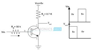
The second is simply using a transistor as a switch. (I found the circuit on web.):
It also worked, meaning that the LED lit up as expected.
However, when 1) made sure they had common ground,
and then 2) hooked the Vin of the second circuit
to the positive side of the speaker, the LED failed to flash,
even though the speaker continued to produce 2Hz clicks:

Any suggestions?
My goal was to do exactly what I tried: to make a very simple oscillator
that drove a separate LED (not to make a all-in-one LED flasher).
Thanks,
allaccess
P.S. My apologies for the double-post. It was only after having posted to "General Electronics Chat" that I realized "Electronics Projects Design/Ideas/Reviews" was more appropriate. I would have deleted the original but I can't find any delete post option.
I tried the suggestion of changing R(b) to a 50K pot, and ran it through its' whole range, but to no avail.
Also, how do I contact a moderator? I would like to ask Jim B to remove the locked duplicate thread;
how do I delete my own thread?
thanks
I made the two following circuits, separately, each of which worked great.
The first is a 1-transister oscillator, which worked great. I reduced the ohms of the resister to 470 until it produced
clicks at about 2Hz:
**broken link removed**
The second is simply using a transistor as a switch. (I found the circuit on web.):
It also worked, meaning that the LED lit up as expected.
However, when 1) made sure they had common ground,
and then 2) hooked the Vin of the second circuit
to the positive side of the speaker, the LED failed to flash,
even though the speaker continued to produce 2Hz clicks:
Any suggestions?
My goal was to do exactly what I tried: to make a very simple oscillator
that drove a separate LED (not to make a all-in-one LED flasher).
Thanks,
allaccess
P.S. My apologies for the double-post. It was only after having posted to "General Electronics Chat" that I realized "Electronics Projects Design/Ideas/Reviews" was more appropriate. I would have deleted the original but I can't find any delete post option.
I tried the suggestion of changing R(b) to a 50K pot, and ran it through its' whole range, but to no avail.
Also, how do I contact a moderator? I would like to ask Jim B to remove the locked duplicate thread;
how do I delete my own thread?
thanks
Attachments

Last edited:
")

