Continue to Site

Welcome to our site!

Electro Tech is an online community (with over 170,000 members) who enjoy talking about and building electronic circuits, projects and gadgets. To participate you need to register. Registration is free. Click here to register now.

  • Welcome to our site! Electro Tech is an online community (with over 170,000 members) who enjoy talking about and building electronic circuits, projects and gadgets. To participate you need to register. Registration is free. Click here to register now.

Whats a semiconductor substitute for a Relay?

Status
Not open for further replies.

thecritic

Member
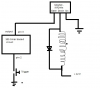
I am trying to design an Electric Door Opener. I am using a solenoid electromagnet to release the door lock. I used a relay in parallel to a capacitor to switch the electromagnet for some time (2 seconds) after I press a push button.

**broken link removed**
(the thich wires carry 5 amp current)

This circuit worked fine for some day. But Since the solenoid would draw 5Amp Current, the relay sparked heavily and was soon rendered uncunduction due to carbon-blackening.

What I want to do now, is use some devices like High Power Mosefet or something like that instead of the relay. So I am seeking your suggestion on this matter.
Also I will be using a 555-timer IC to time the no. seconds to swith on the solenoid.
 
You pretty much answered your own question, a Mosfet can easily be used in place of a DC relay, you'll need to use a diode across the coil to prevent the high voltage from destrorying the mosfet, if you're not currently using one on your solenoid that may be a big part of what's killing your relay in the first place.
 
You pretty much answered your own question, a Mosfet can easily be used in place of a DC relay, you'll need to use a diode across the coil to prevent the high voltage from destrorying the mosfet, if you're not currently using one on your solenoid that may be a big part of what's killing your relay in the first place.

Thanks for your reply. Yeah, I got triggered that the solenoid would spark heavily when switching it off, rather than when switching it on(back-emf !)

So, I guess I should modify my circuit this way.
**broken link removed**

But Would you please tell me the product No. of a common Mosfet that can be use here?? Also, of what votage rating should I use my diode?

(Edit: Oops, I don't think that the diode I inserted will prevent sparking in the relay, or damaging the mosfet)
 
Last edited:
Attached is a simple image of how a protection diode is supposed to be used. Simply replacing the transistor with a Mosfet rated for 5+ amps is all you need to do. Any general purpose power switching mosfet will do. What voltage are you using as you'll need 10volts or better to fully turn on most power mosfets. Also what are you using a capacitor in parallel with the relay for? EMF protection?
 

Attachments

  • flyback_diode.gif
    flyback_diode.gif
    2.9 KB · Views: 1,068
Last edited:
Once the circuit is modified so a MOSFET will survive, keep the relay. It will last forever if properly protected.
 
What voltage are you using as you'll need 10volts or better to fully turn on most power mosfets. Also what are you using a capacitor in parallel with the relay for? EMF protection?

I am using 12 volts. I used the capacitor so that it would hold the relay for some time even if the push-button was already released.

I recently searched some place and got to know about the mosefet IRFZ.
http://www.datasheetcatalog.org/datasheet/irf/irfz44n.pdf
But I am not sure about How I use it. Should I supply + or - to the source??
 
Attached is a simple image of how a protection diode is supposed to be used

Should the protection diode be used accross the relay (as you have shown) or accross the solenoid. !!!???
My problem was the sparking in the relay terminals due to solenoid (not shown in your figure).???
I am not concerned about damaging of other components from the high voltages due to relay coils.
 
mneary he's modifying the circuit to use a mosfet so he doesn't have to use a relay =\ The diagram I posted was just a quick one I grabbed off the net to show the placement of a protection diode on an inductive load, the relay in that schematic would actually be the solenoid he's using. Though with a protection diode properly in place over the existing relay the problem may go away.
 
[quote = "sceadwian"]
What voltage are you using as you'll need 10volts or better to fully turn on most power mosfets. Also what are you using a capacitor in parallel with the relay for? EMF protection?
[/quote]
I am working on 12v system.
I use the capacitor so that the relay will be turned on for sometime even after releasing the push button.

I searched a few place and came accross a mosfet IRfz44n.
http://www.datasheetcatalog.org/datasheet/irf/irfz44n.pdf
But I am not sure about How i use it. Should I connect + or - to the source?
 
If you're going to keep the relay you would put them across both the relay trigger coil, and the solenoid. The one on the relay protects the transistor or whatever you're switching it on with and the one on the solenoid will eliminate the back EMF when the solenoid is switched off. You probably shouldn't be using a capacitor in that manner. Can you provide a complete schematic of how you have things hooked up currrently? To get the kind of behavior you're describing so far you should be using a 555 to trigger the relay or mosfet that feeds power to the coil.
 
Last edited:
The IRFz44n is rated to almost 50 amps, that's overkill to say the least.
 
Though with a protection diode properly in place over the existing relay the problem may go away.

I am not still sure about how the protection diode will work. As far as I know, the sparking was caused when the relay in operation (carrying 5Amp Current through the solenoid) was swithed off their by trying to break the circuit. It is the nature of solenoid (inductior) to resist the change in current. So, to keep the current moving a large contact potential is established in the relay terminal which give rise to spark.

So, After I place a diode accross my inductor and try to switch off the operating relay, the current will try to carry on, and since it (current) can't move through the diode, it will move through the relay, and hence the sparking!!!

Whats the big point I am missing here???
 
thecritic, I think you need to go back to electronics 101.
The diode will do absolutely nothing when power is applied to the solenoid because it will be reverse biased and the solenoid will function normally. When you cut the power to the solenoid it resists the current change by creating an inverse voltage potential, this forward biases the diode causing it to conduct, basically short circuiting the solenoids terminals. This causes the current the magnetic field produces as it collapses to run around in an endless circle in the coil through the diode till it all dissipates as power in the resistance of the coil, walla, no arcing. It's needed on both the relay primary AND the solenoid, because they're both inductive loads.

Forget about the fet for right now, the diodes alone may solve your problem.
 
Last edited:
Here is a thumnail of where I have reached so far.
**broken link removed**

Am I correct ?
 
Last edited:
Should the protection diode be used accross the relay (as you have shown) or accross the solenoid. !!!???
It's needed on both the relay primary AND the solenoid, because they're both inductive loads.
A diode should be placed as shown across any large inductive load, both solenoid and relay.
So, After I place a diode accross my inductor and try to switch off the operating relay, the current will try to carry on, and since it (current) can't move through the diode, it will move through the relay, and hence the sparking!!!
If the diode is hooked up properly (as shown by Sceadwian), the current will flow through the diode until it has decayed.
 
You'll want a 10k resistor going from the gate of the mosfet to ground, this helps protect the gate when the circuit isn't operating. Also in your schematic you have the +12 and the GND lines reversed. Source should be grounded directly and the load should be between the drain and +VCC.
 
Also don't use rectifier diodes as flyback protection, you'll want to use a fast diode, basically the highest current rated signal diode you have. Regular diodes take a little while to turn on when the voltage chances abruptly, at least in comparison to the sudden very high voltage the coil produces. A modest ceramic cap in parallel with the diode will further dampen the voltage spike from the solenoid, as it will conduct a decent amount of current during the high rise time of the inductive spike, enough to soften it for the diode a pinch.
 
Last edited:
Status
Not open for further replies.

New Articles From Microcontroller Tips

Back
Top