Continue to Site

Welcome to our site!

Electro Tech is an online community (with over 170,000 members) who enjoy talking about and building electronic circuits, projects and gadgets. To participate you need to register. Registration is free. Click here to register now.

  • Welcome to our site! Electro Tech is an online community (with over 170,000 members) who enjoy talking about and building electronic circuits, projects and gadgets. To participate you need to register. Registration is free. Click here to register now.

What makes power sensors so expensive?

Status
Not open for further replies.

E63

New Member
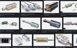
I have been shopping for a proper group of power sensors, but I find them to be outrageously expensive.

After watching a few tear down videos, I still fail to understand what makes these so pricey. Can anyone fill in the blank for me here? I would like to understand where all this money is going.
 

Attachments

  • fgffg.JPG
    fgffg.JPG
    154.5 KB · Views: 200
I don't work in this area but a little bit related.
What frequency are you wanting to measure? What wattage?

You need a high wattage shunt that is good from DC to gHz. That is not easy to make and not easy to probe it work right.
The volume is low. These are not sold in a 6-pack.
Some measure RMS power and that is hard at gHz. If you are OK with average power the price is better.
 
At one time, HP make a microwave power meter that detected the heat rise in a load resistor to determine the power (perhaps someone still does).
Thus it gave a true-RMS reading independent of the wave-shape, even for pulses.
 
I don't work in this area but a little bit related.
What frequency are you wanting to measure? What wattage?

You need a high wattage shunt that is good from DC to gHz. That is not easy to make and not easy to probe it work right.
The volume is low. These are not sold in a 6-pack.
Some measure RMS power and that is hard at gHz. If you are OK with average power the price is better.

I am thinking of this as I would a set of socket wrenches. Different sizes for different needs. I had in mind a set of probes, older ones, that would cover the general spectrum, perhaps a set of 3 or 4 etc, that could be added to over time.

When I break these down, there is still a very limited amount of material being dealt with here to create on of these probes. It must mean it has some gold buried in it I cant see or the R and D on these is outrageous... which it can't be. Its not that highly specialized a tool. There are millions of them out there.


Above if you are a builder....


Regards, Dana.
 
At one time, HP make a microwave power meter that detected the heat rise in a load resistor to determine the power (perhaps someone still does).
Thus it gave a true-RMS reading independent of the wave-shape, even for pulses.
Memories of the old HP 431 and HP 432 power meters along with their measuring heads (mounts).

Measuring true power is not an easy task especially over a wide frequency range. This adds cost. I used them with the 478A thermistor mounts. The accurate measurement of true power doesn't come inexpensive. If you want inexpensive I would be looking at old used lab stock.

Ron
 
I can imagine its not an easy task, but nonetheless it fails to explain the prices of these meters.

Just a simple parts breakdown tells you a general cost of one of these, and that's still a fraction of the overall cost.
 
I can imagine its not an easy task, but nonetheless it fails to explain the prices of these meters.

Just a simple parts breakdown tells you a general cost of one of these, and that's still a fraction of the overall cost.
If you think it's so simple, then make your own - you're too used to the give away prices of modern electronics, accurate test equipment over a HUGE frequency range is neither simple nor cheap.

Your 'simple' parts breakdown is also almost certainly entirely wrong - there's nothing 'simple' at GHz frequencies.

Perhaps it's why I am asking?

My parts breakdown is simple, but quipping "nothing is simple" at Ghz is not?

Is there an explanation of what makes Ghz expensive in relation to the design and production of these meters, or is this the chance for someone to show the "new guy" the social hierarchy?
 
Perhaps it's why I am asking?

My parts breakdown is simple, but quipping "nothing is simple" at Ghz is not?

Is there an explanation of what makes Ghz expensive in relation to the design and production of these meters, or is this the chance for someone to show the "new guy" the social hierarchy?
You need special (and expensive) components to work at GHz frequencies, you can't just use standard resistors etc. as they have too much inductance and capacitance. UHF and above is more plumbing than electronics.

If you're just wanting a low frequency (short wave, and perhaps up to VHF?) dummy load, you can get away with using non-inductive 'normal' resistors, and there have been countless DIY examples over many decades - building them in tin cans full of oil has always been a popular option.
 
Is there an explanation of what makes Ghz expensive
The most basic system needs a dummy load to create the heat to be sensed.
That dummy load must have a low SWR (a good impedance match) over the frequency range of the sensor.

That is itself is not easy at GHz frequencies; eg. a precision load I had for around 10HGz some years back was a length of WG16 waveguide with a tapered wedge of lacquered wood in it!

It may not sound complex, but it had to have been assembled and tested / calibrated / the certificate and specification plate etc. for that particular unit all done individually by someone in the factory, using who knows how many tens of thousands of pounds worth of calibrated equipment for that frequency band, to be able to test and calibrate each dummy load unit, that they probably sold a few dozen of each year.

If it has been a power meter detector, it would also have had to be run and tested at multiple power levels, each run long enough to get a stable reading - and the whole thing re-worked if it was out of the permitted specifications at any point.

(Note that any particular size of waveguide only works over a certain range of frequencies, basically one octave, but such as load may have a more restricted range depending on its design).
 
  • Like
Reactions: E63
If you're just wanting a low frequency (short wave, and perhaps up to VHF?) dummy load, you can get away with using non-inductive 'normal' resistors, and there have been countless DIY examples over many decades - building them in tin cans full of oil has always been a popular option.

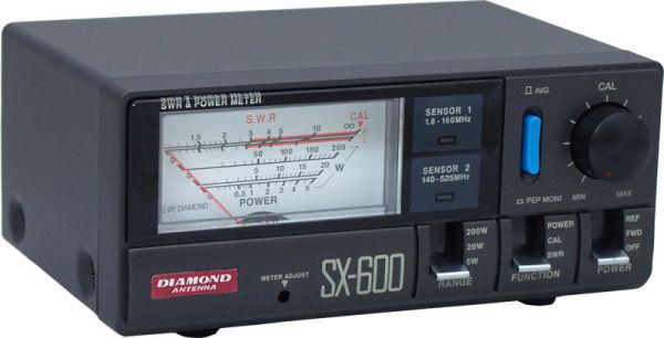
Or for that range, an off-the-shelf inline SWR and power meter - I have a dual sensor one that covers from short wave through to over 500MHz, one of this series:

Add a simple dummy load if you want power measurement without an antenna connected - this is a DIY one of the style Nigel mentioned:

That one even has a detector included for direct power measurement, through to the low VHF range probably.

(I have a couple of DIY loads similar to that plus a commercial water cooled UHF one I got at a junk sale ~30 years ago).
 
The most basic system needs a dummy load to create the heat to be sensed.
That dummy load must have a low SWR (a good impedance match) over the frequency range of the sensor.

That is itself is not easy at GHz frequencies; eg. a precision load I had for around 10HGz some years back was a length of WG16 waveguide with a tapered wedge of lacquered wood in it!

It may not sound complex, but it had to have been assembled and tested / calibrated / the certificate and specification plate etc. for that particular unit all done individually by someone in the factory, using who knows how many tens of thousands of pounds worth of calibrated equipment for that frequency band, to be able to test and calibrate each dummy load unit, that they probably sold a few dozen of each year.

If it has been a power meter detector, it would also have had to be run and tested at multiple power levels, each run long enough to get a stable reading - and the whole thing re-worked if it was out of the permitted specifications at any point.

(Note that any particular size of waveguide only works over a certain range of frequencies, basically one octave, but such as load may have a more restricted range depending on its design).

You're saying that the outer ring not directly associated with the manufacture is expensive, which it is. With different specifics, all other test equipment also have similar spends to develop those tools. And many operate in the Ghz range.

I'm still not understanding how the costs add up like this, and after all these years of technical evolution, manufacture improvements, we still have the same outrageously expensive tools to measure power with?

This is soon to be conquered by the almighty Amazon-Xhinajunk-express, watch. Remember when we could have only dreamed of having a video microscope? So did Leica.... now they get to feel the Xhinajunk pain as a result of not addressing a market of home gamers that want branded and reasonably priced tools that sacrifice apex level accuracy. They wont get the branded part, as Amazon has taught them to trust the Xhinajunk.
 
What I am designing now, you cannot get it in a box from Amazon. It comes with an application engineer that sets it up and calibrates it.
Engineers have shown it in many trade shows.
Bill has spent months writing the manuals. Both for hardware and software. Just for this version. Each version needs a different set of manuals. Instruction videos etc.
The software boys in Germany have 3 years invested in it.
There is the "machine". Its big brother in process. The little sister. The older versions (prototypes) of each.
There are people in US, Germany, Japan, China each working on a piece or version.
Each group has a manager, technician, engineers, writer, coder, ...... salespeople on every continent.
Because we are inefficient and large there is a 3x markup. Stockholders want money, security, heat, new roof, parking lot, repair department .......

Parts are F....ing hard to get. In China they are paying $100.00usd for a $10 part. I purchased a year ahead and am OK on my end.
I cannot just get a "51 ohm resistor". I need a certain resistor. 1% or 0.1%, temperature stable, made in a certain way. You probably know that resistors are lazer trimmed by a zig zag pattern (that increases the inductance) but I can not have the inductance at these frequencies. There for I need special parts.
I am using (in certain places) thin film resistor mounted upside down on the board. You know that lead length effects inductance. Even on surface mount resistors lead length is a problem. The distance from the bottom side the resistor to the top and back down adds inductance. By mounting the resistor upside down I shorten the distance.
In one spot I have resistor where the connection is not on the ends of the part but on the side. Long Side resistors have less inductance.
Each capacitor has been analyzed for resonant frequency, L, R, Q, stability with temperature, stability with changes in voltage.
The PCB is where most of the thinking is. Each via adds 1.4nH to the connection. Some of the connections are transmission lines having 50 ohms impedance. Thought is put into current flow in ach layer and how they effect each other. In a number of places current flows in the Top Layer and must return in L2, 0.1mm down in an exact matching trace. Some times a trace takes the long path to delay the signal a little. I have 1500V and 200A mixed in with mV traces. There are open spots in the PCB to hold off 5000V isolation and I can not have the PCB house write their name in copper there. (or anywhere)
There are man decades of effort (recently) built on top of 80 years of past work.
The priced Bill Of Material is nothing in the great plan. If you saw last years FedEx and DHL bill you will know why the price is what it is.
 
1. These are made in relatively low volume.

2. These are generally commercial products. If you make a consumer product, you can make any kind of claim you want and nobody seems to care. The other day I saw a battery pack that could "power any appliance" for $99. If you make a commercial product for engineers to use, you have to actually deliver the specified performance.

3. You're making the mistake of thinking that price is some function of cost. A properly set price does not reflect the cost to the seller but the value to the buyer.
 
What I am designing now, you cannot get it in a box from Amazon. It comes with an application engineer that sets it up and calibrates it.
Engineers have shown it in many trade shows.
Bill has spent months writing the manuals. Both for hardware and software. Just for this version. Each version needs a different set of manuals. Instruction videos etc.
The software boys in Germany have 3 years invested in it.
There is the "machine". Its big brother in process. The little sister. The older versions (prototypes) of each.
There are people in US, Germany, Japan, China each working on a piece or version.
Each group has a manager, technician, engineers, writer, coder, ...... salespeople on every continent.
Because we are inefficient and large there is a 3x markup. Stockholders want money, security, heat, new roof, parking lot, repair department .......

Parts are F....ing hard to get. In China they are paying $100.00usd for a $10 part. I purchased a year ahead and am OK on my end.
I cannot just get a "51 ohm resistor". I need a certain resistor. 1% or 0.1%, temperature stable, made in a certain way. You probably know that resistors are lazer trimmed by a zig zag pattern (that increases the inductance) but I can not have the inductance at these frequencies. There for I need special parts.
I am using (in certain places) thin film resistor mounted upside down on the board. You know that lead length effects inductance. Even on surface mount resistors lead length is a problem. The distance from the bottom side the resistor to the top and back down adds inductance. By mounting the resistor upside down I shorten the distance.
In one spot I have resistor where the connection is not on the ends of the part but on the side. Long Side resistors have less inductance.
Each capacitor has been analyzed for resonant frequency, L, R, Q, stability with temperature, stability with changes in voltage.
The PCB is where most of the thinking is. Each via adds 1.4nH to the connection. Some of the connections are transmission lines having 50 ohms impedance. Thought is put into current flow in ach layer and how they effect each other. In a number of places current flows in the Top Layer and must return in L2, 0.1mm down in an exact matching trace. Some times a trace takes the long path to delay the signal a little. I have 1500V and 200A mixed in with mV traces. There are open spots in the PCB to hold off 5000V isolation and I can not have the PCB house write their name in copper there. (or anywhere)
There are man decades of effort (recently) built on top of 80 years of past work.
The priced Bill Of Material is nothing in the great plan. If you saw last years FedEx and DHL bill you will know why the price is what it is.

Thank you. I appreciate the detail in highlighting what must be an almost endless list. It takes me back to a previous point... there are multitudes of lab gear with highly specialized and sensitive components that are either very expensive or labor intensive. In terms of a bill of materials, the meter just isn't enough of a black swan.

We said that kind of thing about Xinajunk, but they are a body of companies "platformed" by amazon that never had to invest in any of that tech they "are influenced by".

Your point is well taken about complexity, but I am not swayed in my view about the cost breakdown of these meters. And that its a relatively stable technology that didn't price drop. I think it's because it's a profit center, like printer ink.
Unfortunately, if I am correct, we are not far from the new XinaXunk S4 Hot Selling Super Power Meter with specs just close enough.
 
never had to invest in any of that tech
There are people in China that take a data sheet and copy the example circuit out of it. They make a circuit without really knowing what it does. They don't even know how to test it. But they can advertise it on Alie for $4.98.

I designed part of a Signal Generator. I want one but the cost is high. I now have a clone of it. No manual. Works OK but not as good. They did not invest the big money into new ideas. They did not make the PC --- Signal Generator software work. Cannot be controlled over the internet. Does not talk to a scope. Some RFI noise. But for 1/10 the price it works for what I want it to do.
 
No. That's what successful Research/Engineering companies do as opposed to those who copy/steal someone else's IP and clone them.

There is this executive position at Polaroid I want you to interview for...

Wait, Kodak just called...

Xerox, line one...

Music companies got away with this kind of thing for a long time, but are widely hated, and many even gloat at the theft of IP via sharing.
 
Last edited:
Status
Not open for further replies.

New Articles From Microcontroller Tips

Back
Top