Continue to Site

Welcome to our site!

Electro Tech is an online community (with over 170,000 members) who enjoy talking about and building electronic circuits, projects and gadgets. To participate you need to register. Registration is free. Click here to register now.

  • Welcome to our site! Electro Tech is an online community (with over 170,000 members) who enjoy talking about and building electronic circuits, projects and gadgets. To participate you need to register. Registration is free. Click here to register now.

What is this part

Status
Not open for further replies.
Can you tell me what would be the value of the inductor.
I have placed a photo of the inductor with this post
Thank you very much for your input as it is very informative
 

Attachments

  • IMG_3082.JPG
    IMG_3082.JPG
    302.2 KB · Views: 125
You've got bigger problems than the inductor! Have you fixed the diodes?
You replaced the zener diode D1 and D2 (I just noticed you said it was 1n4733 which is a 5.1v zener) with 1n4007 and got D1 reversed.

Get the diodes fixed and test it, why are you messing with the inductor?

Hey and why is your "Reputation" bad???? :(
 
Can you explain why my reputation is bad as I am not awear of this.
I have tried to follow the rules of the forum an do the right tink by every person
Greg
 
Last edited:
I have altered the Circuit diagram as you recommended.
Had a look at the circuit diagram of the monostable and I can see where the drawing is much simpler than the one I have drawn.
The transistor 2N5232 NPN I have replaced with a 2N2222 Q1 and Q2
and the signal diod I am using a IN4148 is this ok.? for the above also.
I have placed a attachment of the modified circuit diagram.
I hope that it is correct
Thank you Greg
 

Attachments

  • IMG.jpg
    IMG.jpg
    339.7 KB · Views: 159
I have checked the transistor's one has 2N5232 which is a NPN
The other is 2N5234 but the 4 has been scratched on the body I have tried to find a data sheet to compare the both transistors but with no luck.
Are they both the same.
Can I use the 2N2222 NPN transistor.
There is a inductor do i need this inductor to test the rev counter.
If i do require this part then how do i work out the value as the one i have dos not giv a reading on a inductance meter.
Greg
 
Last edited:
Generally the type of the 2 transistors won't matter too much they are both only connected to low voltages and switching low currents. Any 2 small NPN should be ok.

The inductor is just a hash filter on the input. As long as it conducts (is NOT open circuit) then you can assume it is working ok.
 
The picture shows a typical "coil wound over axial" with fairly fine wire. I'd try a 330uH or 470uH which should be fine.

Its unusual for that inductor to fail, it will be rated at 100+ mA maybe even up to 500mA and even with a worse case miswire of +12v to tacho ground and ground to input the 390 ohm resistor would have limited inductor current to about 30mA.

So when is this thing going to be operational?
 
Excuse my question but you mentioned to use a 330 uH or 470uH Inductor .
I was looking in the parts book and found the inductor but it was under the RF Chokes / Inductor.
Is there any difference in a RF Choke Inductor annd a inductor.
Greg
 
Generally "RF chokes" are smaller and used for signals, inductors larger and used in power supplies but they are the same thing. In your circuit it only requires a small choke/inductor capable of 200mA or so.
 
Thanking you all for your help with this project . I will be testing the unit out on the week end and hope that there is no smoke. I will let you know a I have replaced all the components except the veriable resistor
 
Taco

I have installed the taco and the trim pot will not trim the unit enough to 0 the needle .
Replacing R1 with a bigger value will this bring the unit back to 0 and enable me to adjust the trim-pot.
There is a circuit diagram in this post that I drew up .
Can you advise me regards this problem.
 
Last edited:
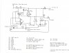
Try increasing the value of R2, it seems a little low.

To make the gauge read zero Q2 pulls the voltage low, and it will never reach as low as 0v, but increasing R2 reduces Q2 "on" collector current so you will get a lower reading. That type of tacho probably never read exactly 0v anyway, or maybe was mechanically compensated at the dial spring.
 
Thank you for your help and advice as to what happens when R2 value is increased,as I have trouble understanding that area of circuits.
Is there a web sight that has Circuits to show what direction the voltage goes and what it does.
I know what the function of the component are and can draw Circuits but what happens when voltage is applied and to track the voltage and what voltage drop is expected
This is a area I need help with Can you help me with advice.
Thanks again.
 
Status
Not open for further replies.

Latest threads

New Articles From Microcontroller Tips

Back
Top