Continue to Site

Welcome to our site!

Electro Tech is an online community (with over 170,000 members) who enjoy talking about and building electronic circuits, projects and gadgets. To participate you need to register. Registration is free. Click here to register now.

  • Welcome to our site! Electro Tech is an online community (with over 170,000 members) who enjoy talking about and building electronic circuits, projects and gadgets. To participate you need to register. Registration is free. Click here to register now.

What is this part

Status
Not open for further replies.

Gregory

Member
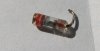
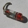
I have a glass diod I think it may be a sigenel diod but it has color bans around the length of the component'
The bands are black;gray;black;red when I test it with analog multi meter it tests like a diod but I do not undrstand how to read the colour's
Do you use the resistor colour coads to determan the value If so what is the value as on a normal diod there is a band on one end,Do you take this band as part of the rading,
Can the value of the component be determend by a digital or analog meter.
 
Last edited:
There are no standard colour codes on diodes. It does sound like a small signal diode, so treat it as such. It could be a zener diode, the only way to test that is to gradually increase the reverse voltage to it with a high value resistor in series until it starts conducting, you'll know because the voltage across the diode will stop going up will stop going up. If it's just a small signal diode you can replace it with pretty much any other small signal diode and the circuit should still work, err on the side of caution use a small signal diode that has a relativly high current handling ability.
 
If you use the standard resistor code it would be 2080 (right to left as you listed them). A 1N2080 is a general purpose 50V, 500mA diode, so that may be what you have.

The band on one end of a normal diode marks the cathode end.
 
this is a photo of the component can you advise me of the value
 

Attachments

  • IMG_3064.JPG
    IMG_3064.JPG
    49.9 KB · Views: 181
  • IMG_3066.JPG
    IMG_3066.JPG
    79 KB · Views: 214
  • IMG_3067.JPG
    IMG_3067.JPG
    429.9 KB · Views: 146
That has got to be one of the best close up photo's of a glass passivated diode I have ever seen =) If it wasn't just a little bit out of focus I'd say it was perfect.

However there is no way to determine it's 'value' it was a small signal diode of some type, the exact type probably isn't important. Just replace it with a generic small signal diode.
 
Another way to narrow it down is to look at the circuit that it is used in.
The forward voltage drop will also tell to a lot. ie: Silicon, germanium, schottky diodes all have a different Vf.
 
Last edited:
If the diode is dead you can't test it.
 
Dos the colours reperesent any thing
The first one is black you can just see the band which i thing is the cathode end then ther is a big gap then gray black and red are the colour bands of any meaning or value.
If the colours do not mean anything I will try a signal diode that has been advisd.
Thank you for your assistance
 
That has got to be one of the best close up photo's of a glass passivated diode I have ever seen =) If it wasn't just a little bit out of focus I'd say it was perfect.

However there is no way to determine it's 'value' it was a small signal diode of some type, the exact type probably isn't important. Just replace it with a generic small signal diode.

That is a great closeup, how did you do that.

Oh, I do not know the answer to your question. Sorry.
 
I used a canon digital camera wich has Macro function and a tripod then Settings on the camera was raw setting then croped the photo and enlarged the final photo to 400 pixeles The lens was 100mm away from the component on a A4 piece o paper in the sunlight.
Hope thiis helps with your inquiry
 
this is a photo of the component can you advise me of the value

It looks like an RF axial PIN diode , I could see a PIN chip inside it ? .Though I am not sure , but where did you get the Diode from , it could be a Varactor diode as well . But the answer could be more precise when you answer where did you get this from
 
If the diode is dead you can't test it.
True. But it looks like the lead has just broken off at the body. Gregory might still be able to get a meter probe on it.
Even if we can't ID the diode, knowing the circuit that it came out of will help us find a suitable replacement.
 
The component in question came out of a electronic rev counter of a old boat.
I will try to place a photo of the board boath sides this may help you.
I will also try to draw the circuit If I can and place it on the forum.
as there are 2 transistors that have a number 2N5232 NPN which I can not find a equivelent to and a diod 1N4733A
 
I used a canon digital camera wich has Macro function and a tripod then Settings on the camera was raw setting then croped the photo and enlarged the final photo to 400 pixeles The lens was 100mm away from the component on a A4 piece o paper in the sunlight.
Hope thiis helps with your inquiry

Thanks G... Cool pic, gotta love it.
 
The transistor is 70v 100mA silicon NPN
The 1n4733 diode is 5.1v zener

I doubt the glass diode is a 1n2080 as it's unlikely to be a 500mA diode in that package.
It looks a lot like the old 1970's germanium small signal diodes, I seem to remember they had a black band and sometimes red and black bands.

Either way I'd replace it with a small signal like 1N4148 unless its position in the circuit makes you think its another zener.

PS. Ive fixed a heap of those 2 transistor tachs (and auto tune up meters etc) over the years. They typically use 2 transistors as a monostable that gives a fixed length pulse, powered by a regulated voltage, the old ones use a zener. Each engine coil firing triggers the monostable and the output of the monstable is fed to an analog moving coil meter, the result is a dc output voltage exactly proportional to rpm.
 
Last edited:
I think the 1N4148's might be a good one to try, the reason I thought it was a small signal diode is cause those look pretty similiar to the 4148s I have.
 
I am a bit slow getting back to you but I am very slow at drawing a circuit from a board.
I have a circuit diagram that I have posted of the taco.
I am not shore if the EBC on the transistors are correct and I do not know the value of the Inductor.as there is a open circuit on this part.
The glass diode that has been posted I have replaced with a signal diode but I am not shore about this replacement
Can you advise me of the Diod and the inductor and the EBC of the transistors on the circuit are in there correct position
All the parts are listed below on the circuit diagram.
I hope the circuit diagram can help.and is correct.
Thank you greg.
 

Attachments

  • IMG.jpg
    IMG.jpg
    589.7 KB · Views: 177
Ok, it looks like a standard 2 transistor monostable multivibrator tacho, i've seen heaps of them over the years. The lower 2 diodes are signal diodes, 1n4148 is ok for these. The top diode is a zener to give the regulated PSU voltage, iit goes from +pwr to ground and you have it reversed.

If that is the diode you replaced you need to find a zener, try something about 9.6v or so.

You got the transistors wired wrong, for Q1 its base receives the input pulse from D3, so you should reverse C and B, then E is to ground which is right.

With Q2, make E go to ground, and C go to R3 (and out to the meter), so reverse C and E.

You did pretty good drawing the circuit out, it's not an easy task. :) If you want to tidy it up, google for "2 transitor multivibrator monostable" which will show you a neat way to draw the 2 transistors.

These 2 transistor tachos are typical in old stuff, each input pulse from the vehicle coil just triggers the monostable, which makes a fixed timed period. Then the output is integrated (smoothed) and fed to a voltmeter, so the average DC volts always represents RPM. Hence they require a regulated power supply voltage, which is the job of the zener. You can improve its accurace by using a 7808 (+8v regulator) instead of a zener. Some of the "better" auto analysers used a 3 pin regulator to power the monostable.

If you have changed the zener diode the calibration will be off, the trimpot R11 controls the timed period of the monostable which might be enough range to recalibrate it. If not you might need a different zener voltage value. It's unlikely to be a zener less than 6.8v, or higher than 10v.

If you are using this on a different engine you may need to recalibrate it anyway.If you need a large change in recalibration you can change C1 which is the monostable timing cap.

Hope that helps. :)
 
Status
Not open for further replies.

Latest threads

New Articles From Microcontroller Tips

Back
Top