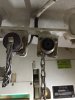
It's probably a mil-c-5015c circular connector, which is common in shipboard installations which this may be from the picture. These come with various numbers of pins, in configurations with different keying options. A mating connector will be expensive, typically with contacts, body and back shell being supplied separately.


 ).
).