Continue to Site

Welcome to our site!

Electro Tech is an online community (with over 170,000 members) who enjoy talking about and building electronic circuits, projects and gadgets. To participate you need to register. Registration is free. Click here to register now.

  • Welcome to our site! Electro Tech is an online community (with over 170,000 members) who enjoy talking about and building electronic circuits, projects and gadgets. To participate you need to register. Registration is free. Click here to register now.

What is the configuration of this circuit (op-amp)?

Status
Not open for further replies.
Hi,

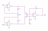
I got a circuit for EKG system. It amplifies an input-voltage up to x202 scale. What's the configuration of the circuit below? Any formula to calculate the amplification?

At first i tried to use 2 OpAmps, with Inverting Amplifier configuration (x -10, x -20) and put it in series, in a hope that i could get a scale factor of x200. But the output turns out to be square wave rather than sine wave . LOL could u tell me why?
 

Attachments

  • EKG-amplifier.gif
    EKG-amplifier.gif
    17.4 KB · Views: 827
According to the schematic, the midband gain is 100, with a -3dB bandwidth of 0.16Hz to 22Hz.

U1A, U1B, U2B, R2, R3, R8 and R9 make up a differential amplifier with a gain of -10. U2A, R5 and R6 make up an amplifier with a gain of -10.


The midband output voltage is

OUTpos=[-INpos*(R3/R8) + INneg*(1+R3/R8)*(R9/(R2+R9))]*(-R6/R5)

Gain=OUTpos/(INpos-INneg)

Since R2=R8=10k, R3=R9=100k, R5=100, and R6=1k, the midband gain is, as I said, 100.

The low frequency corner is Fc1=1/(2*pi*R10*C1)

The high frequency corner is Fc2=1/(2*pi*R4*C3).
 
What you really need is an instrumentation amp. You can buy these in a single package. You can also make them with 2 or 3 opamps. An instrumentation amp has a differential high impedance input. You can set the gain to up tp about 1000 with a single resistor. Once you amplify the signal with a instrumentation amp you can add opamp gain stages to its output to get more gain.

The square wave you are getting is probably 60Hz(or 50Hz in the UK) pickip from the wireing in the building. It looks like a square wave because it is railing your amplifier because of the high gain. To fix this you need to sheild your leads. Wrapping them in aluminum foil that is connected to ground is an easy way to do this. This sounds silly but one of my professors in University worked at a government high energy lab studying Gamma rays and all his equipment is covered with peices of aluminum foil.

You will need a third lead on your amplifier connecting the patient to signal ground through a high value resistor to keep their common mode voltage from floating relative to your amplifier. Again make sure your circuit is battery powered so you don't accidentaly kill yourself.

Hope this helps.

Brent
 
I second the instrumentation amplifier notion :eek: I've actually found example circuits of EKG's using instrumentation amplifiers.

Below is not a specific circuit for an EKG, but it is an example of an instrumentation amplifier, i suggest you start with it.

Vo=(1+ 2R/Rp)(V1-V2)

of course, the R's on the last amp can be adjusted to get the amount of gain you want (the feedback resistor..)

the first stage (the first 2 amps), has a gain, then the second stage (last amp), has another gain... the 2 gains are multiplied, giving you a pretty massive gain. EKG's pick up a really insignificant voltage, so it has to be amplified pretty good.

good luck, google more about instrumentation amps... you might find an example of one that is for an ekg!
 

Attachments

  • InstrumentationAmp.PNG
    InstrumentationAmp.PNG
    7.5 KB · Views: 742
I have found 2 In-Amp, AD623 and AD627, from www.analog.com

both can be configured as single ended. It could save me from finding another negative voltage supply. ^_^

What's the pros and cons of using Single-ended In-Amp, compared to dbl ended in-amp?
 
For single supplies you have to generate a voltage that is half the supply to act as signal ground. This just connects to the REF pin on the Inst amp. Other than that there isn't any really good reason to have dual supplies.

Brent
 
Status
Not open for further replies.

New Articles From Microcontroller Tips

Back
Top