The controlling Hall device is tied to the steering wheel of my OHV, so the mechanical speed is super slow compared to the electronics, OR SO I THINK!
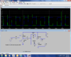
The voltage from the Hall goes up and down from 5.51 which is changed to 5.0 by the first op amp, 1a that is sent to the Pfet drivers , oops- not labelled, LM393 driving P1&P2 and is compared the voltage divided by 2 1Ks and it has a dead band created by the pot. Is that not enough of a dead time to allow the fet to turn off before the other turns on, or am I not understanding properly.
the 5.0 is also mixed with the triangle for the pwm using the same voltage dividing method with the dead band in the middle.
Thanks for the .asc