Continue to Site

Welcome to our site!

Electro Tech is an online community (with over 170,000 members) who enjoy talking about and building electronic circuits, projects and gadgets. To participate you need to register. Registration is free. Click here to register now.

  • Welcome to our site! Electro Tech is an online community (with over 170,000 members) who enjoy talking about and building electronic circuits, projects and gadgets. To participate you need to register. Registration is free. Click here to register now.

What feature are a must and what are worth dropping? (Example)

Status
Not open for further replies.
As in anything, you can have it all if you're willing to pay for it.

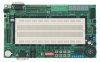
Below is a list of the features available on the Parallax Professional Development Board. It sells for $149US Qty 1 and that doesn't include the stamp. It has lots of bells and whistles but if you had to trim the fat what would you mind losing the least?

Personally I'd keep the RS232, 5V power supply, solderless breadboard, maybe a 10K pot and I'd like to add a 16x1 LCD as standard.
PS it'll have a 16F88 with an ICD2 connector as the CPU (not a stamp)


  • 40-pin DIP socket (for all BASIC Stamp 24/40-pin and Javelin Stamp modules)
  • 14-pin SIP socket (for BS1-IC)
  • 28-pin “skinny” DIP socket (for SX28AC/DP)
  • USB, DB-9, BS1, and SX-Key programming connectors
  • 2.1 mm, center-positive connector for DC power
  • 5 volt, 1.0 amp power-supply with power switch
  • 16 discrete blue LEDs
  • Five blue 7-segment (with decimal point), common-cathode LED displays
  • Parallel LCD (available separately) may be configured in 4-bit or 8-bit mode
  • Two servo-compatible headers
  • Two 10k Ohm potentiometers
  • Audio amplifier with built-in speaker; with switch for external speaker
  • L293D high-current driver for motors, solenoids, etc.
  • Eight, normally-open pushbuttons (I/O lines protected, and pulled-up to Vdd via 10K)
  • Eight DIP switches (I/O lines protected, and pulled-up to Vdd via 10K)
  • Pulse generator with selectable frequency (1 Hz, 10 Hz, 100 Hz, or 1 kHz)
  • RJ-11 connector; configurable for X-10 and 1-Wire® communications
  • RS-232 DCE port with MAX232E transceiver
  • DS1307 (I2C®) real-time-clock with 3v back-up battery (pre-installed)
 

Attachments

  • 28138.jpg
    28138.jpg
    42.1 KB · Views: 187
What to have on an experimenters board is always a problem, there's no right solution or wrong solution, just individual choices - but regardless, you're likely to be missing something you want, and have some things you don't need.

I put a LOT of thought into it before I started my PIC tutorial series, and came to the (obvious really!) conclusion that the best way is a modular system. The next problem was how to implement it, initially I considered edge connectors, but eventually decided on the far more versatile method of using plugs and leads. Again, much though was spent on the best way of doing it - and I decided on a ten pin Molex connector - ten pins so you can have a complete port on a single plug, along with 5V and 0V, giving a single connection between different boards.

As for your LCD, I would suggest a 2x16 rather than a 1x16, a more common display, although they all work 'almost' identically anyway.
 
blue is an eye catching color, however they are expensive. it seems the single quanity prices may be similar, but the production quanity prices are often 2-3x or more than their boring red, yellow or even green counterparts... and a blue 7 segment must cost a LOT more than the red version.

I'd drop all those different sockets ... the sockets themselves don't cost much but the board space does ... perhaps you can substitute them with a single 2x20 header, and sell different socket modules that snap into that header.

i'd also consider dropping the USB unless you'll have a usb to serial chip onboard ... supporting usb in-chip is often beyond the beginner and intermediate level.

deffinately go with 2x16 or 2x20 for the lcd
 
Hi,

Like Nigel did, I'm desgning my own (for the PIC series) and he hit the nail on the head. I've also decidede on a modular system, albeit with certain 'must haves' on the main board, power, rs232, USB connector (for bootloading/contorl) and headers, lots and lots of headers. One massive 40way socket header for attaching a piggyback board and for plugging in wires (just like your board has around the breadboard). A 10 (2x5) pin header for every port, and various 3-6 pin headers for SPI/I2C/PWM/UART etc..

I did find that board when I was googling for idea's, and it seemed a pretty reasonable price for what it is, and yes blue 7-segs are terribly expensive, probably 15UKP for 5 (27USD?) but it has the essentials and more. The best thing about it is the sockets around the BB, very handy! And you could always knock up some cables with pin headers to external boards. I'm still desgning mine, because I'm indecisive :( If you're into the basic stamp jobs, and use a BB regularly with it, I'd say go for it. Although...does it come with the Basic Stamps? or would you buy them seperately? added cost... But the idea of 'modules' instead of single micro's (with ICSP connector/xtal etcc on board) did attract me for a while.

My two pence,

Blueteeth.

Ps, sorry to advertise another post, but my topic is still open...I simply can't decide on thing apart from hundreds of connectors for externals :(
 
William,

I would remove anything that has BS or SX from your list. If you want to have sockets for uC on the board, I would keep the ones that seem to do a lot. I like the 12F683, 16F88 and maybe (have not done anything with it) the 877a.

Push them to the pic chips. And better is ICD2 work with them.
 
Serial can hook up to GPSs and other kits. USB will pretty much only hook up to something with an operating system. Plus I want to offer it as a kit. I prefer soldering DIPs to SSOP or TSOP.

Here's what my prototyping kit will be based on.

The Dolphin Rev B with a Experimentor 350 Solderless Breadboard.
 

Attachments

  • Dolphin B.gif
    Dolphin B.gif
    82.6 KB · Views: 185
Last edited:
Looks good.

I'd include a miniature 12mm diameter direct drive Soberton GT111P piezo speaker. This has pretty much become a "standard feature" on each of my designs. I use it for audio feedback 'clicks' when turning a rotary encoder, or for short beep and double beep feedback on 'short' and 'long' switch presses (double function switches), or plain old alarms.

Mike
 
Mike said:
Looks good.

I'd include a miniature 12mm diameter direct drive Soberton GT111P piezo speaker. This has pretty much become a "standard feature" on each of my designs. I use it for audio feedback 'clicks' when turning a rotary encoder, or for short beep and double beep feedback on 'short' and 'long' switch presses (double function switches), or plain old alarms.

Mike
There will be a "bag" of loose parts. I'll be sure to include one. Can you drive it directly off PIC I/O?

Geeze I'll have to omit yet another power pin... Might as well put a IR detector onboard...

PS get your board yet?
 
Yes, you can drive the Soberton GT111P directly from a PIC I/O pin.

Did you ship me a board? Cool. I'll keep an eye out for it. Thank you.

Mike
 
Go to either 4 or 6 digits on the 7-segment displays, 5 is a dumb number. 4 is enough for many things but you can't do a 6 digit clock with 5 digits.

Also, all those black sockets around the main breadboard don't work very well with anything smaller than 22 gauge wire, 24 gauge is too loose to make a reliable connection. I know, I have one of these boards.

You could probably lose the 10k pots, unless they are exactly what you need, they are a waste. Easier to put what you want on the breadboard. You could also say the same about the discrete LEDs, the motor driver, the audio amp, the buttons, and the switches. Might be better just to double the breadboard space.

- Rick
 
Here's the revised Dolphin rev D 16F88 or 18F1220 (note the pinout is quite different on a 18F1220)

I'm keeping the RS232 port as unlike USB you can hook it to so much more. Example: GPS or even a XPORT dongle... **broken link removed**

Going to start on the PCB, Hopefully keeping it in a Hammond 1591G (4.7" x 7") mount. Might even leave some mounting holes for LEGO. :rolleyes:
 

Attachments

  • Dolphin D.gif
    Dolphin D.gif
    94.2 KB · Views: 150
no onboard clock for the pic? shoe-horn a 20mhz ceramic resonator in there somewhere ;)

oh and what is the full bridge rectififer for? is that intended to make the power supply connection polarity independent, or so it can be powered off AC? filter caps don't really look big enough for AC.
 
justDIY said:
no onboard clock for the pic? shoe-horn a 20mhz ceramic resonator in there somewhere ;)

It's got an internal oscillator, it's NOT a crystal one, but it is accurate enough for most uses - adding an external one means you lose two I/O pins.
 
I've deliberatly left off many cool devices. Many 2 pin devices (so easy to add to the solderless breadboard) IE squeaker, LDR, Thermistor, caps, resistors...


The LCD will be standard. Backlit too. You can demo PWM on the backlight.
A DE9 RS232 with handshaking and pin 9 power option.
4 LEDs & 4 Switches with pullups
6 User ports (or can use as 10K pullups)
A Pot for the A/D or comparator.
An IR for some advanced projects.
Expansion port, (maybe a SD adapter, RS485 or L293 motor driver)

You should be able to demostrate most if not all the features of the PIC with only a few jumper wires and a resistor or two. And build a few fun projects to boot.

Should be easy to find 100s of projects

I'll probably offer a free PCB per month for the best project built around a dolphin...

Now I MUST update my very neglected website.
 
Sound cool.. Has ICD2, I will have to get one. How far out are they? How much? AND what color ;) I like blue.. You should do them all in blue, nice tie in with the website.
 
Nigel Goodwin said:
It's got an internal oscillator, it's NOT a crystal one, but it is accurate enough for most uses - adding an external one means you lose two I/O pins.

that's true ... I forgot the target audience.

hey, there's a gizmo for William to sell as an add-on ... a little breakout board with a Maxim EconOscillator ... programmable via the 1-Wire protocol, it'll generate any clock the user needs.
 
Seems my dolphin is similar to this design

http://www.dhmicro.com/product.html

Seems the buzzer was the choice ;) on that design.

I went for IR & and a pot.

As for SDA & SCL it's a slave I2C on the 16F88 not a master. Pity. I did sneak in the pullups on USR1-6 though.

New heres a very rough PCB layout to fit in a hammond 1595 sloped case.
 

Attachments

  • Dolphin D Beta PCB.gif
    Dolphin D Beta PCB.gif
    21.1 KB · Views: 203
  • 1595.gif
    1595.gif
    21.7 KB · Views: 157
Last edited:
Status
Not open for further replies.

Latest threads

New Articles From Microcontroller Tips

Back
Top