Continue to Site

Welcome to our site!

Electro Tech is an online community (with over 170,000 members) who enjoy talking about and building electronic circuits, projects and gadgets. To participate you need to register. Registration is free. Click here to register now.

  • Welcome to our site! Electro Tech is an online community (with over 170,000 members) who enjoy talking about and building electronic circuits, projects and gadgets. To participate you need to register. Registration is free. Click here to register now.

What does this capacitor do exactly?

Status
Not open for further replies.
Hi

A friend of mine has asked me to convert an RF amplifier to 4m for him.

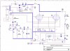
The circuit is attached - I didn't draw it, it is off the web from a site that shows you how to do the conversion.

My question is - What does C7 and the AM/SSB switch do??

There seems to be a voltage doubler rectifier (D6 D7 etc) which turns the transmit/receive relay (K1) to 'transmit' - OK so the circuit detects an incoming RF signal and assumes that you want to transmit.

But all C7 seems to do is to delay the switch on and delay the switch off? What has that to do with AM/SSB? As I understand it you can filter off the carrier and the upper sideband frequencies and still send all you need but using much lower power - but what has that to do with this rectified signal?

I'm confused but I'm sure there is some obtuse reason - anyone help?


James
 

Attachments

  • bremi cct.jpg
    bremi cct.jpg
    102.2 KB · Views: 298
C7 is switched into the circuit for SSB. When you are using AM mode, there is always TX power when the transceiver is keyed. The circuit, that C7 is in, is to switch from Rx to Tx when the transceiver supplies power to the amplifier. This way you don't need a PTT signal from the transceiver . When there is no Tx power, the amplifier is out of the RF circuit because K1 is de-energized and the received signal can get from the antenna to the transceiver without being blocked by the PA.
When transmitting SSB, there is no, or very little, TX power when the operator is not speaking. C7 keeps the PA in the circuit between syllables and words by keeping TR1 turned on between RF peaks. Without C7 the relay would click on and off fairly rapidly as the operator was speaking during TX.
EDIT: I just noticed that the diodes ( D6 & D7 ) are backwards. It won't work as drawn. D1-4 are also backwards. D5 too. Hmmm. I'm no tube expert, so there could be errors in the tube section too. Better triple check before you build this.
 
Last edited:
Where did you get this circuit? It is a disaster. There are so many thing wrong with it I lost count.
 
C
When transmitting SSB, there is no, or very little, TX power when the operator is not speaking. C7 keeps the PA in the circuit between syllables and words by keeping TR1 turned on between RF peaks. Without C7 the relay would click on and off fairly rapidly as the operator was speaking during TX.

Hi kchristie

Thanks for that -It makes sense and ties up beautifully with what the circuit seems to do.

Also you have just made SSB come into focus for me a little more! I hadn't quite tumbled to the fact that there wouldn't be any SSB signal at all if there were no modulation! - Slaps forehead!

But that begs another question - I read a lot that an amplifier gives out say 10W on CW but 40W on SSB (something like that) Why is that? Surely the SSB signal into the amp still looks like the carrier but just at a slightly lower frequency (When the operator is speaking that is).

Thanks
James
 
Where did you get this circuit? It is a disaster. There are so many thing wrong with it I lost count.

Hi Both

I assume that the circuit was drawn by someone tracing out the wiring on his own amplifier so that actual circuit may be different from what has been drawn. The amp has been sold commercially for many years, though with widely differing reviews!

His circuit will be in error as the amp itself works fine - well it did but seems to have given up since I started playing with it!

Cheers
James
 
That has to do with the plate dissipation of the tubes used it the final amp. In the circuit you posted, the tubes are TV horizontal sweep tubes which have a very marginal plate dissipation rating. The output power de-rating for key-down CW compared to SSB is because the peak to average power in SSB is much lower than for CW. Since the tubes are so easily vaporized, the drive level for CW must be much lower than it can be for SSB. The peak envelope power for SSB can be 2 to 3X than that during a CW DAH because the average power in the SSB voice signal is roughly 1/3 of the peak power.
 
Final Question

As a follow-up in case anyone knows - One of the valves glows blue slightly when transmitting. The blue glow comes from a small rectangular aperture in the anode (the box bit in the middle of the valve). Looks like the fire in the firebox on a steam loco but glowing blue if you like. It's not a glow around anything it looks the same as the heater glow - but much less intense and blue!

Sorry for the long dribbling explanation but I've been reading about valve 'glows' on the web and the description is often so poor that you can't visualise what is being described!

Incidentally the 'getters' are still a healthy silver.


Cheers
James
 
Basically, the amplifier puts out the same, average total amount of power for both AM and SSB. The thing with AM is that AM consists of the carrier and two side bands so the power is spread out more. Only one side band is required to transmit intelligence and the carrier contains none. So basically, with SSB, you are concentrating all your power in a narrower bandwidth where the intelligence resides.
 
Last edited:
That has to do with the plate dissipation of the tubes used it the final amp. In the circuit you posted, the tubes are TV horizontal sweep tubes which have a very marginal plate dissipation rating. The output power de-rating for key-down CW compared to SSB is because the peak to average power in SSB is much lower than for CW. Since the tubes are so easily vaporized, the drive level for CW must be much lower than it can be for SSB. The peak envelope power for SSB can be 2 to 3X than that during a CW DAH because the average power in the SSB voice signal is roughly 1/3 of the peak power.

So the output power rating being quoted is the peak power and assumes something about speech. I assume that if you were to issue a loud continuous high pitched scream into an SSB transmitter you could then overdrive the transmitter as your 'speech' would approach a 'continuous' modulation?

Excuse the laboured/pedantic approach but I do like to understand things fully!

Thanks
James
 
Where did you get this circuit? It is a disaster. There are so many thing wrong with it I lost count.

I see now that the circuit diagram that you posted was drawn by someone other than the original maker. There are many errors in that diagram. Since the amplifier "worked" (illegally in the US CB band, I might add), the errors in the schematic must have been made by the guy tracing the schematic.

Just a few of the errors I spotted: The keying diodes are backwards. The high voltage diodes are backwards. D5 is backwards, The PiNetwork in the output is totally screwed up. The loading capacitor does nothing for SWR, etc, etc.

Thanks Mike - The diodes aren't too misleading but I'd like to get the Pi part right. I assume that one side of C14 and C15 should go to 0V to make a Pi along with L3? Which is the 'loading' capacitor, what function does that have? I'll retrace that part of the circuitry.

Thanks again
James
 
So the output power rating being quoted is the peak power and assumes something about speech. I assume that if you were to issue a loud continuous high pitched scream into an SSB transmitter you could then overdrive the transmitter as your 'speech' would approach a 'continuous' modulation?

Excuse the laboured/pedantic approach but I do like to understand things fully!

Thanks
James

Yes, with these sweep-tube amplifiers, a loud whistle into the mic (which on SSB makes a signal which is the equivalent of key-down CW) was often enough to melt the plates in those TV tubes. Running into a seriously mismatched antenna could do it, too.

btw-these things were horrible TV Interference generators. I see that you are converting it to 75MHz. Unless you understand what "neutralization" is, this thing could wipe out chan 2-6 TV (and even FM broadcast) reception for miles around.
 
btw-these things were horrible TV Interference generators. I see that you are converting it to 75MHz. Unless you understand what "neutralization" is, this thing could wipe out chan 2-6 TV (and even FM broadcast) reception for miles around.

Have to confess I am totally new to RF! Just looked up neutralisation and it seems that common grid circuits don't normally suffer from it.

Would the effect on other systems be due to harmonics generated by distortion/non-linearity in the amplifier? Again, I'm no RF expert but shouldn't the output frequency be in controlled limits?

Sorry to follow one question after another but I'm learning a lot, but the more loose ends I gather the more other loose ends seem to be relevant, and thus require tying!!


James
 
Have to confess I am totally new to RF! Just looked up neutralisation and it seems that common grid circuits don't normally suffer from it.

Would the effect on other systems be due to harmonics generated by distortion/non-linearity in the amplifier? Again, I'm no RF expert but shouldn't the output frequency be in controlled limits?

I used to be on the TVI committee of the local ham club. A lot of TV interference complaints led to a CBer bootlegging an amplifier. Come to think of it, since it is a grounded-grid amp, the TVI was likely second harmonic of 27MHz clobbering TV Channel 2 (54-59MHz).
 
Status
Not open for further replies.

New Articles From Microcontroller Tips

Back
Top