Continue to Site

Welcome to our site!

Electro Tech is an online community (with over 170,000 members) who enjoy talking about and building electronic circuits, projects and gadgets. To participate you need to register. Registration is free. Click here to register now.

  • Welcome to our site! Electro Tech is an online community (with over 170,000 members) who enjoy talking about and building electronic circuits, projects and gadgets. To participate you need to register. Registration is free. Click here to register now.

What Colpitts oscillator is this?

Status
Not open for further replies.

Elerion

Member
Hi everyone.

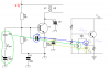
I've come accross an oscillator circuit (first attached image, left), which is very similar to a common collector crystal Colpitts oscillator (right).
But it is not a common collector, as the load (hf transformmer) is placed in the collector node and output is taken from there.
Not sure what it is.

This is my guess.
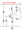
It looks to me like a common base. (second attached image).
The feedback is then via collector-emitter capacitance.
The crystal is not in place of the inductor, but on the base, so it resonates near its series resonance frequency (effectively grounding the base).

What do you think?
Thanks!
 

Attachments

  • colpitts.png
    colpitts.png
    76.6 KB · Views: 244
  • cb.png
    cb.png
    19.5 KB · Views: 263
It just looks like a regular Colpitts with emitter feedback, a fairly common configuration. With the output taken from the collector, neither emitter, base nor collector is really a common point, but from the point of view of oscillator function, I would call it a common collector.

Edit: Or, maybe phase splitter would be more accurate.
 
Yes, it makes sense.

Any idea why that inductor in series with the xtal?
It must be some kind of frequency compensation, but I've seen many many circuits like this, with the variable capacitor but no inductor...
 
the feedback path is from a capacitive divider, that's what makes it a colpitts. using an inductive divider (usually a tapped inductor) would be a hartley.
 
Any idea why that inductor in series with the xtal?
The variable capacitor is in series with the crystal to adjust the frequency (slightly) so that it is exactly on its required frequency.

Adding the inductor increases to frequency pulling range.
If the inductor is selected to be resonant with the variable capacitor and circuit strays, as the capacitor is adjusted, the reactance in series with the crystal can be changed from capacitive to inductive.

Where did you find this circuit?
Sometimes this configuration with the inductor/capacitor in series with the crystal is referred to as a VXO (Variable Crystal Oscillator).

JimB
 
Any idea why that inductor in series with the xtal?
probably to insure the crystal oscillates at the fundamental rather than an overtone (harmonic).
 
believe it or not, there is a [textbook] on the subject of crystal oscillators.
 
believe it or not, there is a [textbook] on the subject of crystal oscillators.

Yes. "Practical Oscillator Handbook" is good one too, not only crystal related.

Adding the inductor increases to frequency pulling range.
With a 50 pF variable cap I can slow down the frequency a couple of kHz.
Strange... I thought that adding series capacitor increases crystal's resonance frequency.

Where did you find this circuit?

It is part of an amateur CW transmitter.
 
You've mentioned one of my favorites...."Crystal Oscillator Circuits" by Robert Matthys (Kreiger Publishing 1992). Very practical and useful book.

the more digging i do at archive.org, the more buried treasure i find.....
 
Status
Not open for further replies.

Latest threads

New Articles From Microcontroller Tips

Back
Top