hi pic2pic,
I have programmed two 16F877 with the program you have posted, the version that has PORTA has the switched inputs and the LED's on PORTB.
It works OK, no sign of any flashing, the PORTB output of one PIC follows the byte set on PORTA of the other PIC, works OK both ways on both PIC's.
Its possible the version of the program you have not posted, the version that uses PORTB as the switch input and LED's on PORTA is at fault.
Please post the FULL version of BOTH programs..")
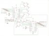
and if possible a circuit diagram, showing the interconnection of the two PIC's and the byte select switches.
I have programmed two 16F877 with the program you have posted, the version that has PORTA has the switched inputs and the LED's on PORTB.
It works OK, no sign of any flashing, the PORTB output of one PIC follows the byte set on PORTA of the other PIC, works OK both ways on both PIC's.
Its possible the version of the program you have not posted, the version that uses PORTB as the switch input and LED's on PORTA is at fault.
Please post the FULL version of BOTH programs..
and if possible a circuit diagram, showing the interconnection of the two PIC's and the byte select switches.
Last edited: