Continue to Site

Welcome to our site!

Electro Tech is an online community (with over 170,000 members) who enjoy talking about and building electronic circuits, projects and gadgets. To participate you need to register. Registration is free. Click here to register now.

  • Welcome to our site! Electro Tech is an online community (with over 170,000 members) who enjoy talking about and building electronic circuits, projects and gadgets. To participate you need to register. Registration is free. Click here to register now.

Waveform analysis...

Status
Not open for further replies.

randolfo

New Member
Could somebody help me on this circuit with waveforms, i am not sure if i am getting it right. the schematics is attached..I have 2 questionnares..

Which of ff. statements are correct ?
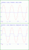
1) to get waveform3 at the output of this circuit, both sw s1 and sw s3, is to be closed.
2) to get waveform 3 at the output of this circuit, either sw s1 and sw s3 must be closed.
3) to get waveform3 at the output of this circuit, only sw s2 must be closed.
4) no combination of closed switches will produced waveform 3.

As far I could understand i go for no. 1 ?

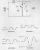
2) Which of the ff. waveforms will be produced when only S1 closed?
1. waveform 2
2. waveform 3
3. waveform 4
4. waveform 1

Again i go for no. 1 ?

Please help and clarify . thank you.
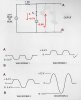
 

Attachments

  • scan0001.jpg
    scan0001.jpg
    396.2 KB · Views: 388
For waveform 3, you must remember that a normal zener diode will conduct like a normal diode in the anode positive, forward direction (about 0.7V drop). It only acts like a zener in the reverse bias configuration (positive on cathode, negative on anode). Given that, is it then possible to get waveform 3 with the given circuit? Look at the voltage drop across each diode for each polarity of the signal source.

Based upon the above information, then your answer when S1 is closed is also not correct.
 
clarification..

I don't get this statement - Look at the voltage drop across each diode for each polarity of the signal source. ?

It is AC so it must alternate between positive and negative , right ?
When s1 is closed, it should forward biased the diode it must be positive ?


its kinda of hard..:)
 
I don't get this statement - Look at the voltage drop across each diode for each polarity of the signal source. ?

It is AC so it must alternate between positive and negative , right ?
When s1 is closed, it should forward biased the diode it must be positive ?
Sorry if I wasn't clear. By each polarity, I meant the positive and negative transitions of the AC signal, so that you can determine what the diodes are doing for each half of the waveform. From that you can determine what the output should look like.

I could, of course, tell you the answers, but it's better if you can figure them out yourself. It's not really complex. Just determine what each diode is doing as the signal source goes between positive and negative. Remember that the diode with the lowest voltage at any particular time will determine the output voltage.
 
I have read some text about zener diodes, it conducts as normal diode on forward bias and it will conduct also in reverse diode when breakdown voltage was reached. The graph is almost flat in reverse bias until the breakdown voltage was reached. So, based on my limited analysis , the correct waveform would be Waveform No. 3, Am i interpreting this correctly or I am missing something ?
 
I have read some text about zener diodes, it conducts as normal diode on forward bias and it will conduct also in reverse diode when breakdown voltage was reached. The graph is almost flat in reverse bias until the breakdown voltage was reached. So, based on my limited analysis , the correct waveform would be Waveform No. 3, Am i interpreting this correctly or I am missing something ?

hi,
Which switch/s is closed for the question you are asking.??
 
I am asking about the question no. 2, based on the characteristics of zener diode i just mentioned, the correct answer should be waveform no. 3 ? I am not sure though :)

hi,
Look at this edited image of your circuit, you should be able to work out the answer, give it a try and post what you think is the answer.:)
 

Attachments

  • scan0001.jpg
    scan0001.jpg
    133 KB · Views: 243
hi,
Look at this edited image of your circuit, you should be able to work out the answer, give it a try and post what you think is the answer.:)

Sorry, my knowledge in electronics still limited. But on question no. 2 , i would go for the waveform no. 1 , because the diode has lowest voltage in reverse so it determines the output waveform...wheww.

On question no. 1 , I would go for answer no. 4 . No combination of closed switches will produce output waveform 3..

Headache...:D . How am i doing ? is enough ?
 
Hello,


It should be noted that in some beginning classes in electronics the diode is considered to conduct with ZERO voltage drop. What this means for these problems here is that the teacher may be looking for a 'reverse' conduction voltage of zero instead of 0.7v which occurs in real life. That's the way some courses are.
Otherwise, none of these waveforms would work for any of the conditions given.
 
WOW mral thanx for writing me back! i know my school isn't quite as effective as i'd like and it really helps to have some input.
i guess figuring out what theyre "looking" for is really half the battle.
let me bounce this off you. with switch 1 closed you would get wf 1 because the zener (acting like a normal diode) would only allow the negative part of the cycle through while clipping the negative peak due to it's own saturation??

as for reproducing wf 3, im still not sure why it wouldnt be possible.
again thanx for your help. you dont know how lucky i feel to have found a place where i can ask these questions.
 
ok so i took the test and i chose 1. the reason i think so is simpl because it's backwards and as mr al said it's all about what they want to teach on a given day.
the reason i came to why th third wf isnt possible is because it's no a complete clipper circuit if it were s1 and 2 would have to be closed and the diode would have to have been back to back.

flyin colors. the other questions such as the phase shift oscillator questions that randolf had asked didn't come out so well. i should have stuck to my previous answers.
hell of a resource though! thanx fellas. im sure ill be back!
 
Hi pup,


Well i guess you came to the right place then :)

Yes, with sw1 closed you get wf1, that's right. The only caution here is that some zeners that are made to be voltage references have an internal reverse connected Si diode to help temperature compensate the overall device. These kinds of zeners will not conduct in the reverse direction, or at least very very little. I assume that we are not talking about those kind here though because again none of these circuits would work right :)


Waveform 3 is possible, if you take into account that it is probably not drawn 'exactly' right, and also that the type of zeners being used are the type with the internal reverse Si diode present. With switches 1 and 3 closed, that is roughly the wave you would see except the lower half of the wave is drawn kind of badly. It should be drawn to look more like a clipped sine wave, clipped at both positive and negative peaks. The actual drawing looks a little strange that's all probably because it is not drawn true to what it should look like...although it is somewhat close to what it should be.

If on the other hand, you assume that the type of zeners are the type that conduct in the reverse direction (mostly the type you find around today) then waveform 3 is not possible because both diodes would conduct in reverse and limit the voltage to only plus and minus around 1 volt or sometimes a little higher. That's because one diode would clip in reverse while the other diode didnt even get a chance to get high enough to operate as a normal clipper yet.

Here is a pic showing the effects of the two different types of zener diodes with switches 1 and 3 closed...
(Note: V2 is the input sine wave and Vo1 is the output voltage)
 

Attachments

  • ZenerClipping.gif
    ZenerClipping.gif
    23.4 KB · Views: 181
Last edited:
Hi pup,

You're welcome my friend, and i wish you very good luck in your future electronic studies.
 
Status
Not open for further replies.

Latest threads

New Articles From Microcontroller Tips

Back
Top