Continue to Site

Welcome to our site!

Electro Tech is an online community (with over 170,000 members) who enjoy talking about and building electronic circuits, projects and gadgets. To participate you need to register. Registration is free. Click here to register now.

  • Welcome to our site! Electro Tech is an online community (with over 170,000 members) who enjoy talking about and building electronic circuits, projects and gadgets. To participate you need to register. Registration is free. Click here to register now.

Water sensor help urgent required !

Status
Not open for further replies.
is this circuit corrosion free if yes then please explain how it is using DC POWER SUPPLY.
KMoffett has already said it is corrosion free.
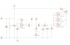
The probes are connected via C2 and C3 to the rest of the circuit. DC is blocked by those capacitors and as the oscillator output voltage rises and falls the capacitors couple an alternating voltage to the probes. The period that either probe is positive is approximately equal to the period that it is negative, so there is negligible net DC, thus preventing corrosion.

1) Have you provided a true earth connection (e.g. to a water pipe) to the circuit as I suggested?
2) Having properly earthed the circuit does the LED still come on with one probe immersed, when you are nowhere near the circuit? If so, is it the probe connected to C2 or the one connected to C3?
3) Why are you "moving this circuit in the air"? Keep it still.
4) Don't use long wires (which act as antennas) to connect to your circuit.
5) Use a battery to power the circuit; not a mains-powered supply.
 
Hello allec how do i earth the pipe properly please give some image so i can understand properly. And my tank is on terrace(top flor) and i want the circuit to be in middle flor so friend it will need long wire.And another things is if i use 9 v dc battery so how many month it will work using 24hrs.
 
The pipe was an example only. Do the sockets of your mains electricity supply have an earth pin? If so, use that as the earth connection.

I suggested using a battery as a way of eliminating one possible source of interference which might be the cause of your problem. If the LED operation is ok with a battery supply then the mains power supply is the culprit and will have to be modified for use as a battery replacement. If the LED operation is still erratic with a battery supply then we will need to look elsewhere for the culprit.

Having the probes on one floor and the circuit on another floor is a recipe for disaster. You must use short wires from the probes to the circuit. A screened twisted wire pair would be good. You can, however, have the LED a long way from the rest of the circuit. Ideally the whole circuit should be in a screening box.

thanks for your reply.. Ya i have earth connection in my socket but how would i connect to pipe please explain by drawing images.. And what is the meaning of screening box.. And what is your email id..
 
If you have an earthed socket you don't need to connect to a pipe: connect the circuit to a socket earth pin instead (as per post #43). In the photos you posted I couldn't see any earth wire connection.
A screening box is a metal enclosure connected to an earth pin.
Just post if you have a query (I don't disclose my email id in posts).
 
Sorry friend i dont have earth i thought you are talking about negative power supply.. So kindly accknowledge...
 
If I had meant the negative supply I would have said so.
I specifically referred to the sockets of the mains electricity supply. Surely your domestic supply, which provides 110V AC or 230V AC (or other Volts AC) has an Earth connection? Use that.
 
And another things is if i use 9 v dc battery so how many month it will work using 24hrs.
The quiescent current for your circuit with a 9V battery is ~0.9mA. With a red LED and a 1K LED resistor in the water-detected condition the current draw is ~8mA. With about 500mAH battery capacity the circuit could work for about 4-5 weeks if no water is detected. Much less if the LED is on for any length of time.

Also, one thing you will find, running the oscillator at lower frequencies will result in less problems with false alarms from capacitive coupling between wires to electrodes. Running my oscillator at 250Hz (R=560K and C=10nF), I was able to run 20' of single-pair 22GaA cable to the circuit with no alarm. If i coiled the wire in a 6"diameter spool it did alarm. As stated do a short run to between the circuit and the electrodes, and a long run to the LED.

Ken
 
Last edited:
Hello alec i dont have ground in my main socket so what should i do .. And kmoffett i want to run from 6 volt nokia charger not the battery.
 
Besides using a lower frequency the sensitivity might be adjusted for optimum using a fixed resistor of 47K and a trim pot of 100K.

Refer to the revised schematic.

Boncuk
 

Attachments

  • WATER-PROBE.png
    WATER-PROBE.png
    28.3 KB · Views: 143
  • WATER-PROBE-BRD.png
    WATER-PROBE-BRD.png
    19 KB · Views: 132
Ok FRIEND I WILL MAKE AGAIN AND I WILL TELL YOU IF ANY PROBLEM OCCURS.
AND I AM NOT USING JUMPERS TO JOIN THE CONNECTION ON BREADBOARD I AM USING SOLDERING WIRE (WHICH IS YOU FOR SOLDERING) TO JOIN ALL TRACK..
 
keep your probes as short as posible, otherwize thay will act like antennas.
Is this a metal tank? how are you planing to attach the probes?
 
FRIEND I HAVE FOUND A WATER SENSOR CIRCUIT DIAGRAM ON FOLLOWING SITE :
http://www.circuitstoday.com/simple-water-level-idicator

PLEASE HAVE LOOK AT SUGGEST A GOOD IDEA ?
WILL THIS CIRCUIT WORK AS I DESERVE CORROSION FREE .....
AND SUGGEST GOOD IDEA ....

AND SECOND THING I HAVE FOUND A ELECTRODELESS WATER SENSOR ON FOLLOWING SITE :
http://www.discovercircuits.com/DJ-Circuits/electrodelessh20mon1.htm

AND THIRD IS :
http://www.electronic-circuits-diagrams.com/alarmsimages/6.gif

PLEASE SAY WHICH ONE IS BEST + CORROSION FREE AMONG ALL THE CIRCUIT ABOVE AND WHICH I HAVE MENTIONED IN PREVIOUS POST..
PLEASE ACKNOWLEDGE :
 
Last edited:
Hello 4pyros I am not using metal tank I am using plastic tank .. but I am only adding 5 inch wires which is working as electrodes..
AT least i want 50cm long wire which will work as electrodes... because my tank is huge..
In 5cm also it is working as antenna ...
 
hello allec as you said in previous post :
(Having properly earthed the circuit does the LED still come on with one probe immersed, when you are nowhere near the circuit? If so, is it the probe connected to C2 or the one connected to C3?)
yes it is the probe C3.... as i immersed in water the led light ..
 
Hi yusuf,

have you tried my suggestion yet?

Boncuk
 
Hi Boncuk i have made the circuit which you have send and it worked best. Thanks my friend very............. much and alec you also..
Well i have posted some circuit diagram links in my previous post which is just above.. And kindly accknowledge..
 
Timer Help ?

Hello here I have a timer circuit please tell how many minutes timer circuit it is.

thanks in advance
 

Attachments

  • timer.PNG
    timer.PNG
    11.9 KB · Views: 151
Last edited:
That circuit is unnescisarily complicated and I think you would be better off using a single gate. If you are using a 4093 it is a schmitt triger circuit so all you need is a resistor on the output connected to a capacitor. Have both of the inputs to that gate going to the junction between the resistor and capacitor.

The frequency is equal to 1/1.1*R*C
 
The circuit as draw is just hard for me to read. A circuit similar to this one is what I believe Dragon Tamer is suggesting. The CD4093 is a quad schmidt trigger NAND gate. The timing is shown in the drawing.

Ron
 
Last edited:
Status
Not open for further replies.

Latest threads

New Articles From Microcontroller Tips

Back
Top