Continue to Site

Welcome to our site!

Electro Tech is an online community (with over 170,000 members) who enjoy talking about and building electronic circuits, projects and gadgets. To participate you need to register. Registration is free. Click here to register now.

  • Welcome to our site! Electro Tech is an online community (with over 170,000 members) who enjoy talking about and building electronic circuits, projects and gadgets. To participate you need to register. Registration is free. Click here to register now.

Water sensor help urgent required !

Status
Not open for further replies.
I can't tell from the pics; is your circuit assembled on perforated-only board or on perforated board having copper strips?

hi alec.
Its isolated copper doughnuts, I avoid using it.
 
Its isolated copper doughnuts, I avoid using it.
I would, too. I've never come across it (I lead a sheltered life!). Seems neither flesh nor fowl.
 
hey alec please help friend how should I complete this project ? this circuit is not working...
?
please..................... help...
 
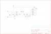
The circuit can be made to work (as has been stated in a previous post, and as shown by simulation). We are trying to help, but before we can go any further we need your answers to our questions in previous posts, and confirmation that you (1) are using only one IC, (2) have a high resistance DVM for your measurements, (3) have grounded all unused IC inputs, and (4) ensured by measurement that there is V+ (6V DC) at pin 14.
 
ok friend thanks :
This the answer of your asked questions:
1)I am using 2 IC because this is there in circuit diagram.
2)Yes I have high DVM for mesurments.
3)No I have not grounded all unused Inputs pins because this is not mentioned in circuit diagram.
4)Yeah ? I am getting 6V Dc on pin 14.

So please suggest a good idea to this problem...
and
thanks in advance
 
As alec_t said, there four gates in each IC. You only need two of the gates in one IC.

Still not good enough pictures to troubleshoot your circuit. :(

Ken

Got back a little late.
 
Last edited:
I am using 2 IC because this is there in circuit diagram
A circuit diagram is just a 'map': it is not intended to give all the details (e.g. a parts list, assembly instructions) needed to build a project.
If you note the pin numbering carefully in the diagram you will see that the first NAND gate of the 4093 uses pins 1, 2 and 3 whereas the second gate uses pins 4, 5 and 6. Those pins would be considered by most engineers to be the pins of just one 4093 IC. By using two ICs you are making the circuit more complicated than it need be. I suggest you remove one of the ICs and remake the circuit with two gates from the remaining IC, using the pins as shown in the diagram (which will aid further discussion). It might help you to download and study a datasheet for the CD4093.

No I have not grounded all unused Inputs pins because this is not mentioned in circuit diagram
See my comment above about the purpose of a circuit diagram....and then ground them !

At least we know pin 14 is getting the correct voltage. That's a good starting point. Also, your meter seems ok for the measurements you need to track down the problem.
 
friend please send a circuit from where which I can make from 1 IC.
because I am new in electronic and doesn't have better knowledge...
please ....

thanks in advance
 
Last edited by a moderator:
friend please send a circuit from where which I can make from 1 IC.
because I am new in electronic and doesn't have better knowledge...
please ....

thanks in advance


Hi.
You should be able to follow this PCB layout.
 

Attachments

  • AAesp06.gif
    AAesp06.gif
    10.8 KB · Views: 136
Hi Yusuf,
Here is a circuit as requested. It is similar to your diagram but it now makes use of two of the NAND gates (U1, U2) as before, and what were previously two unused gates (U3, U4) are used instead to boost the LED current to make it brighter, as was suggested by KMoffett in post #12. As all the input pins are now being used don't ground any of them.
Connect up pins 1 to 14 of the single CD4093 in this circuit exactly as shown. (I have
numbered all the pins).

WaterSensor.gif

Good luck with the build.
 
Last edited:
ok friend I love you......... thanks for helping me but will this circuit solve the corrosion problem as the electrodes will be in water...
 
ok friend I love you......... thanks for helping me but will this circuit solve the corrosion problem as the electrodes will be in water...

Yes! I've used versions of this circuit concept very successfully with no corrosion of the electrodes. I used stainless steel TIG welding rod for the electrodes. I silver solder/brazed a 1/4" inch area at the top of each electrode so I could use electrical solder to attach the probe wires.

Be aware that Eric's PCB layout and Alec's circuit schematic are not the same. Eric's is an exact layout for the original circuit you posted...with the opto-coupler. Alec's used the extra gates in the IC to drive an LED.

Maybe Eric can modify his to use an LED instead.

Ken
 
Last edited:
Yes! I've used versions of this circuit concept very successfully with no corrosion of the electrodes. I used stainless steel TIG welding rod for the electrodes. I silver solder/brazed a 1/4" inch area at the top of each electrode so I could use electrical solder to attach the probe wires.

Be aware that Eric's PCB layout and Alec's circuit schematic are not the same. Eric's is an exact layout for the original circuit you posted...with the opto-coupler. Alec's used the extra gates in the IC to drive an LED.

Maybe Eric can modify his to use an LED instead.

Ken

hi eric please modify your circuit to drive led.And hello alec i have made your circuit and it is working but it is very sensitive because i not even touch the electrodes just i was very near the led lights.as i go far the led blows off and it's this reapting again and again when i take my hand near and far.i hope this is not good for my water sensor. And i want water sensor circuit which indicates via led corrosion free not that circuit which drives led. And friend try to make good one so that only while touching electrodes the led lights else it does not light while taking the hand near or far.. Well friends thanks for reply..
 
Last edited:
Hi alec,

why didn't you stick to the common name given to ICs with multiple logic gates?

Using U1 through U4 a newcomer will interpret this as being four ICs regardless of pin names.

I suggest to rename the gates U1A trough U1D.

Boncuk
 
Hi yusuf,

you can minimize the corrosion problem by using either stainless steel rods or strips as electrodes. Wires can be soldered directly onto stainless steel if the solder spot has been treated with muratic acid.

After soldering rinse thoroughly with water to avoid damage to the copper wire.

Use stranded wire of sufficient cross section (0.75square mm)

Boncuk
 
Hello boncuk well the circuit which alec has present will it solve this corrosion problem and as i have mentioned in previous post the problem of sensitive by talking hand or mobile near the electrodes lights the led and taking little far away blows off the led. So kindly accknowledge..
 
Hi yusuf,

I have no explanation for the blown off LED other than using long wires for your circuit which might act as antennas. Rectification is done by D1 and D2 allowing to charge C4 with a positive voltage.

If you use a printed board with short connections the issue might be solved. (Who uses his cell phone near sensitive electronic devices?)

Here is a circuit schematic as suggested by Ken and a PCB layout. The PCB is single sided with no wire jumps. It's dimensions are 2.05X1.55".

PM me your email address if you want to obtain the Eagle files.

Eagle light is free of any charge and you can use it to print the PCB scaled 100%.

Boncuk

P.S. I added C5 and C6 for proper decoupling of the IC.
 

Attachments

  • WATER-SENSOR-SCH.png
    WATER-SENSOR-SCH.png
    46 KB · Views: 160
  • WATER-SENSOR-BRD.png
    WATER-SENSOR-BRD.png
    16.8 KB · Views: 131
friend it is acting as antenna the electrodes...
AND WHEN I ONLY PUT ONE ELECTRODE IN WATER THE LIGHT TURNS ON...
i WANT IF i PUT TWO ELECTRODES THE LIGHTS UP ELSE OFFF..
AND WHEN I AM TOUCHING OUTER LAYER OF WIRE THEN ALSO IT IS LIGHTINING AND BY TOUCHING ALSO IT'S LIGHTINING..
PLEASE SAY HOW TO SOLVE THIS PROBLEM
 
@Boncuk
why didn't you stick to the common name given to ICs with multiple logic gates?
Because I was lazy. The circuit was designed using LTSpice and those are the names given automatically by the program!

@Yusuf
Try reducing the value of R2 (say to 1 megohm) to reduce the sensitivity of the circuit; and provide a true earth connection to the circuit ground. Your body is acting as an antenna for RF signals, which get rectified by D2, C4 and switch the LED.
 
Hi allec ok i will try and the second problem is : is this circuit corrosion free if yes then please explain how it is using DC POWER SUPPLY. And second problem is i am immersing only one electrodes in water and the light turns on without immersing second electrodes.. And my third problem is when i am moving this circuit in the air the led glow sometimes and now i am not touching it so i hope it is catching some rf or any type of signal.. SO PLEASE SOLVE THE ABOVE MENTIONED PROBLEMS.
 
Status
Not open for further replies.

Latest threads

New Articles From Microcontroller Tips

Back
Top