Continue to Site

Welcome to our site!

Electro Tech is an online community (with over 170,000 members) who enjoy talking about and building electronic circuits, projects and gadgets. To participate you need to register. Registration is free. Click here to register now.

  • Welcome to our site! Electro Tech is an online community (with over 170,000 members) who enjoy talking about and building electronic circuits, projects and gadgets. To participate you need to register. Registration is free. Click here to register now.

water level controlled motor on/off switch

Status
Not open for further replies.

Lalit

New Member
Hi all,

I need help in designing a suitable electronic circuit that
serves the following practical situation -

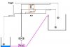
Water is transferred from an underground-sump(ugs) to an overhead-tank(oht) by an electric pump. When the water level in the oht reaches a certain mark(upper limit), the pump is automatically switched off. When the water level in the oht falls below a certain mark(lower limit), the pump is automatically switched on under the condition that the water level in the ugs is above a certain mark.

thx in advance.
Regards,
Lalit :roll:
 
Why do you need an electronic circuit?

Can't you do this with two float switches connected in series ? when the float switch in the sump pump is off ( meaning the water level is low) and the float switch in the tank is on ( meaning the tank needs filling) the motor will not run. When the water level in the sump reaches a set level the motors turns on and starts filling the tank. When the float switch in the tank reaches a set level it will turn the motor off.

If you really want to know how to do it electronically , you can use a window comparator circuit and relays. A window comparator has an upper and lower trip point.
 
a 555 can do the trick, with just a few more components.
if you want the schematic......tell me and i will scan it.
 
I think the reason Lalit want it done that way is so the pump isn't going to be truning on and of all the time, only when it needs it.

is that right?
 
thx and further

Hi nettron1000,bogdanfirst and watty
Thx for ur helpful replies.
Where can i get the schematic of the circuit using -
1)window comparator and relays
2)555 timer
Further, is there any way of solving the problem opto-electronically?
Regards,
Lalit :roll:
 
water as coductor

I came to know from somebody that using the conducting property of water to switch circuits might not always work. How far is it true? What r the possible problems and their causes?
 
Re: water as coductor

Lalit said:
I came to know from somebody that using the conducting property of water to switch circuits might not always work. How far is it true? What r the possible problems and their causes?

thats how my sump pumps are controlled, 2 stainless steel conductors, connected to the base of a PNP transistor, and tiggers a D-flip-flop at high, and resets it at low.
 
Re: water as coductor

Lalit said:
I came to know from somebody that using the conducting property of water to switch circuits might not always work. How far is it true? What r the possible problems and their causes?

Thats true. 100% pure water does not conduct electricity. The more impurities and salts present in it (i.e free ions), better is its conductivity.
 
Hi Lalit,

Yes, using water as a conductor can often give problems.
Such level detectors are widely used, their usual name
over here, England, is 'no-flote' sensors.
Problems such as corrosion, from applications that use
more than a few milliamps, and problems from straggly
bits dangling down and making a conductive path to the
water surface, also a build-up of surface floating
material around the high level mark, even floating dust
seems to cling to the no-flote sensors.
Regular cleaning seems to be the only reliable answer.

The best arrangement i have seen is a bubbling pipe.
Slow air release into the bottom of the tank to be
monitored. The pressure is used to sense the level. Only
plastic tubing goes to the tank, all the electrics are
separate. Needs a small pump like a fish tank pump.
Very reliable. Very little trouble. Tubing has to go
up and over, so that it won't syphon in case of power
failure.

Here is one possible wiring set-up using floats and
contacts. Floats and contacts is probably the most usual
set-up for this job.

If the supply is A.C. use an A.C. relay.
The relay is basic.
The circuit is simple.

If you want to use electronics and transistors and chips
then you will need to get a D.C. power supply to run them.

I have not seen or heard of Opto-electronics being used
for this type of work, but i have heard of Sonics being
used to do this. I think it was where the liquid was an
aggressive chemical, the principle is just echo sounding
and is used on many things, from parking cars to measuring
rooms for estate agents (realtor salesmen ?).

There are also problems with sonics, one of them being
cobwebs, which can cause wrong readings, and moths and flies
which can congregate around the sender/receiver causing
wrong readings.

In my experience, easiest is best. Just use floats and
contacts, inspect it every week or two, problems are easy
to spot and easy to fix. Problems with complex systems can
be a headache.

The accompanying diagram is only one workable circuit,
there are many variations. If the pump is a 3 phase unit,
the relay would need extra contacts.

If a 'Contactor' is to be used, the circuit is simple
enough to use the auxiliary contact.

Best of luck with it,
John :)
 

Attachments

  • Floats.jpg
    Floats.jpg
    13.9 KB · Views: 2,365
There you have it Lalit, i think John nailed it pretty good and a very good illustation to boot.
 
Thank you Nettron,

Though i am now wondering if this question was actually a student
excersise for designing theoretical electronic micro-controller
systems.

Cheers, John :)
 
using transistors

Hi all,
Thx for all the help and advice.
Please see the schematic here :
**broken link removed**
What is the need to have transistors T1,T3 and T5.
Can't we directly connect the bases of transistors T2,T4 and T6 to S,H and L respectively(totally eliminating T1,T3,T5 from the circuit).
I don't exactly understand the need to have VR1,VR2 and VR3 in the circuit. Also what purpose do R1,R2 and R3 serve?
What should be the ideal distance between C & H and C & L in the overhead tank and between C & S in the underground tank ?
Regards,
Lalit :roll:
 
Status
Not open for further replies.

Latest threads

New Articles From Microcontroller Tips

Back
Top