hi tt,
Downloaded your *.rar,,, very slow download for 8.6Mb.
I'll try your asm etc...

EDIT:
Looked thru the source code.
There is no point in working on a complete program if one part of the hardware is not working.
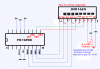
Look at this short LCD diagnostic code.
It was derived within Oshonsoft and it does work in simulation, I dont have a 16F88 on the shelf.
In the code are the PORTB pin assignments for the LCD, almost the same as yours.
As you are working on a project board it should be a simple matter to re configure the LCD pins on your project board,
DONT change the program to suit your existing wiring.
If the LCD does not work with this simple program I would suggest trying a new LCD.
Lets know what you find.
")
BTW: what are you setting the INTOSC freq too.?