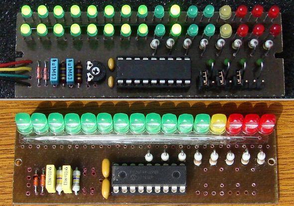
I like to build a VU meter from a PIC micro.Just searched on net & I found couple of projects. Basically I need to show the sound level on 10 to 16 LEDs.
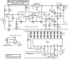
I have some doubts regarding the hardware interface to PIC ADC.The below project used a signal diode and a filter cap feeding to ADC.
 320volt.com
My questions are
*If we feed the audio input from a pre amp output it will not scale to 5V ADC because line out voltages has something like 200-300mV. How is he scaling?
*Does one half wave is it enough?
*How often do I have to read ADC?
I have some doubts regarding the hardware interface to PIC ADC.The below project used a signal diode and a filter cap feeding to ADC.
Microcontroller Controlled VU Meter Circuit – Electronics Projects Circuits
KA2281 integrated circuits, LM3914, etc. According to the vu meter circuits with this circuit has been built on microcontroller circuit pic16f88 stereo really s
320volt.com
My questions are
*If we feed the audio input from a pre amp output it will not scale to 5V ADC because line out voltages has something like 200-300mV. How is he scaling?
*Does one half wave is it enough?
*How often do I have to read ADC?