Continue to Site

Welcome to our site!

Electro Tech is an online community (with over 170,000 members) who enjoy talking about and building electronic circuits, projects and gadgets. To participate you need to register. Registration is free. Click here to register now.

  • Welcome to our site! Electro Tech is an online community (with over 170,000 members) who enjoy talking about and building electronic circuits, projects and gadgets. To participate you need to register. Registration is free. Click here to register now.

Voltage switching for motor power

Status
Not open for further replies.

Huttojb1

Member
Good afternoon all

I have a dc motor which runs at 3-12v at around (peak) 50mA.
I want to switch the running voltage from 12v to 9v to 3.3v (without using PWM).
I draw up a cct using 3 NPN transistor? But it doesn’t seem to be doing what I want?
Does anyone know what is the best way of doing this?
0A0A52B7-DE48-4220-9156-A2BA8F6E7D79.jpeg
 
Sorry, that cannot work; two reasons:

The transistors are in "emitter follower" configuration, which gives current gain but no voltage gain; the emitters will be at around 0.6 to 0.7V below the base voltage regardless of collector supply.

And, you cannot supply a motor from a resistor divider laike that and get a stable voltage; ie. R4 would only pass 4mA if directly shorted to ground.

The motor current will depend on its speed and loading.

To drive a voltage to grounded load from a supply voltage above the logic level, you need two transistors; the first switching to ground, and that switching a PNP or P channel FET with it's emitter or source fed from positive, and the base or gate of that fed via resistors from the collector of the first transistor.

With two or more different voltages feeding the same load, you also need a diode between each PNP collector and the load (motor) to prevent "back feeding" from a high supply to a lower one.

Edit: Thinking about the motor voltage & current requirements, you could use three switch circuits all supplied at 12V, and a couple of eg. 1.3W zener diodes in series with the appropriate transistor switches to drop the voltage at the motor. A 2.4V and an 8.2V zener (in conjunction with the anti-backfeed diodes) would give around 9V and 3V.

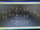
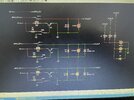
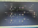
See the right hand half of this example, the high side PNP switch:

MDN1v.png
 
Last edited:
Thank you. I realised the issue with back feeding and put some Diodes in to stop that. But your right with the motor voltage via a pot-div, cannot get it to work.
I changed to relays instead, seemed abit more robust, but now need to look at the voltages and how to get the 12, 8 and 3.3v.
 

Attachments

  • image.jpg
    image.jpg
    3.3 MB · Views: 190
You suggesting something like this?
 

Attachments

  • E5B0A955-00AD-406D-B015-8E9D048B409C.jpeg
    E5B0A955-00AD-406D-B015-8E9D048B409C.jpeg
    4.1 MB · Views: 193
No; the zeners mnust be in series to reduce the supply by that amount. Having them across the supply would cook something, either the zerer or the PSU.
 
Thank you. You suggesting something like this?
 

Attachments

  • 665BB15B-0D7F-4507-BEAD-91B3F1B422E4.jpeg
    665BB15B-0D7F-4507-BEAD-91B3F1B422E4.jpeg
    3.8 MB · Views: 211
Note: voltages do not need to be exactly 12, 8, 3.3. As long as I’m in the ball park, just need a 3 speed motor speed for my application
 
That looks fine!
Don't forget flywheel diodes across the relay coils as well as the motor, when you build it.
Thank you for all your help.
 
Why not use ab adjustable voltage regulator such as an LM317 and switch in different value resistors to set it's output voltage.

Les.
 
Your lower voltage zener diodes will melt with nothing limiting their current with 12V across them.
EDIT: I think motor speed control is done with reducing and regulating the current, not the voltage.
 
Your lower voltage zener diodes will melt with nothing limiting their current with 12V across them.
They are in series with a motor that the OP has stated draws a maximum of 50mA. That's less that 500mW on a 9V zener; I advised 1.3W types to allow for startup and moderate overloads.
 
To be honest, this whole idea is pretty nasty :D

If he's not doing it 'properly' by using PWM, he may as well do it the tried and tested crude way with simple wirewound resistors switched in series for the different speeds, as car heater fans did many decades ago.

I don't think it helps either that we've got no idea what the motor is, what it's actually doing, what it's variations in load might be, or where this 50mA has come from, and under what conditions.
 
Hey all. To answer some of the questions;

50mA is what I have monitored on the motor whilst powered on at 12v. So everything less the 12V reduces the current.

the motor will be used very infrequently and it’s abit of a novelty, on my kit car I have brake biases where it’s a manual knob, the motor will be attached and drive the knob to change brake bias.

this will be done as a novelty and I’m not thinking about changing it whilst driving. Potential when this version is running and I think I want to spend more money on the car I may increase the functionality.

So the method I’m looking at is,
I have an encoder wheel attached to the motor shaft, so for example, if I am on value 0. Request a change in bias, if the value is >50 away, I use the 12v source to drive the motor and monitor the encoder, when I get to <20 away I reduce the speed and then <10 I reduce the speed to the lowest to get the stop without going passed.

I am looking at PWM aswell, but I just want a crude way to see if this works whilst all connected.

hope this explains all and hope this helps.
Thank you for your continued support and I’m open to any advise.
Thank you. Jason.
 
Hey all. To answer some of the questions;

50mA is what I have monitored on the motor whilst powered on at 12v. So everything less the 12V reduces the current.
50mA seems VERY low for a 12V motor.

Does the brake bias knob have to turned lot's of times to take effect?, or just 180 degrees or so?.
 
50mA seems VERY low for a 12V motor.

Does the brake bias knob have to turned lot's of times to take effect?, or just 180 degrees or so?.
Depends on the bias, for full front to full rear your looking 6 turns. But very rare it be changed like that, but that’s worse case.

I’m happy for suggestions, I’m not saying my way is the correct way, it’s just the way I’m thinking.
 
but…. Thinking about it I am monitoring the motor with no load, so maybe the 50mA will increase alittle but not sure it will go that much higher, the load is not a lot of friction
 
Was you thinking a servo motor, already looked at them! Lol
 
Ok.
I have configured the PIC to output a PWM signal and I have wired up a 2N2222a. B to the the PWM via a 1k resistor. C to one side of the dc motor and the E to ground. What’s the best way to configure the hardware. I’m trying to see if using PWM will work.
 
Status
Not open for further replies.

Latest threads

New Articles From Microcontroller Tips

Back
Top