Hi,
Can you verify this is the best design and advise whether a proper voltage reference (LM4040 etc) is the way to go.
Criteria -
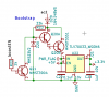
1. Input: 4V - 100V
2. Current: 20mA
3. R31 must be small. The design shown R31/47Kis a 1206 resistor, I'd prefer a 0603 but that requires going up to 100K, fine for the darlington configuration but I'm already pushing the zener way below the minimum current threshold.
The circuit works fine at present. The voltage varies a lot but doesn't go beyond ~5v. I'm concerned however that it's relying hugely on zener tolerance.
Cheers,
A.

Can you verify this is the best design and advise whether a proper voltage reference (LM4040 etc) is the way to go.
Criteria -
1. Input: 4V - 100V
2. Current: 20mA
3. R31 must be small. The design shown R31/47Kis a 1206 resistor, I'd prefer a 0603 but that requires going up to 100K, fine for the darlington configuration but I'm already pushing the zener way below the minimum current threshold.
The circuit works fine at present. The voltage varies a lot but doesn't go beyond ~5v. I'm concerned however that it's relying hugely on zener tolerance.
Cheers,
A.
")