kentken
New Member
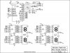
I have a circuit that has 6 dig led display, 6 74hc4511 drivers, and a pic 16F872.
From what I calculate this should draw less then 400ma. But it draws over 600ma.
A 500ma regulator gets to hot and shuts down.
I just put a 1A regulator on it, and the heat sink gets to hot to touch.
What Can cause this? How can I check it?
Thanks
Kent
From what I calculate this should draw less then 400ma. But it draws over 600ma.
A 500ma regulator gets to hot and shuts down.
I just put a 1A regulator on it, and the heat sink gets to hot to touch.
What Can cause this? How can I check it?
Thanks
Kent
")

