Continue to Site

Welcome to our site!

Electro Tech is an online community (with over 170,000 members) who enjoy talking about and building electronic circuits, projects and gadgets. To participate you need to register. Registration is free. Click here to register now.

  • Welcome to our site! Electro Tech is an online community (with over 170,000 members) who enjoy talking about and building electronic circuits, projects and gadgets. To participate you need to register. Registration is free. Click here to register now.

Voltage Monitor

Status
Not open for further replies.

npatel

New Member
Hi,

I want to make a voltage monitor of a 5V battery. So if the 5 V battery goes to say 4.7 V an LED will turn on. I have thought about using a voltage comparator but those need refrence voltages and I only have one source.

Any help would be greatly appreciated.
 
try this:
using V=IR (ohms law)
put a resistor in series with an led so that is only is on when v<=4.7

can anyone make sense of that for us? lol

duno if that will work , just a suggestion
 
i got a schematic using the LM3914 or 15, i dont remember exactly and it shows the voltage from 4.5 to 5.5 usong 10 leds.
interested?
 
Battery Low Monitor

Could a little transistor circuit do the job?

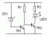
ZD1 provides base current to TR1 and as long as about 0.7v is dropped across TR1's B-E junction it will conduct. This effectively robs the base bias from TR2, turning it off so the LED will be off.

As the battery volts falls below a set value (4.7v ?) the zener will no longer have its (4.7v - 0.7v for TR1 B-E junction = 4.0v) bias, it will stop conducting and so cause TR1 to turn off. TR2 will now have its base current returned and start to conduct so causing LED1 to light.

If the transistors are both BC109 then the hfe is around 500 so R1 can be (4V/(20mA/500)) = 100k
R2 = 4v/20mA = 200R
ZD1 will need some guesses but around 3v9 or 4v1 should do.

Will it work ???
 

Attachments

  • BattMonitor.gif
    BattMonitor.gif
    1.7 KB · Views: 1,179
Mechie,
I got some great results when using a Zener and Variable Resistor and Transistor. I'll post the circuit from home later, but the resolution was down to about .01of a volt if not even less than that.

Eoin.
 
Mechie, you forgot to put current limiting resistor for the zener. Actually it won't matter much since input impedance of transistor is quite high and won't allow much current to flow through the zener. But in other cases where anode of zener is grounded, you can't miss it. :)
 
Zener current limiter

Hi Kinjal :D

I reckon a current limiting resistor in series with the zener will only be required if the circuit is likely to see a voltage of ...
5v for the base-emitter junction + 3v9 for the zener = 9v
and still be expected to alert of a low battery at 4v7

As NPatel stated a 'normal' voltage of 5v and a 'low' of only 4v7 I reckoned that there wasn't enough voltage to play with resistors if we can survive without. The extra resistor would just reduce the circuit's gain.
:wink:
 
Status
Not open for further replies.

Latest threads

New Articles From Microcontroller Tips

Back
Top