hi!
I would like to design a voltage measurement circuit.
What i can understand for now is that i can use the voltage detector IC,BD4850G to measure the voltage which is about 5 V
I'm designing a board to measure the voltage of the electrical appliances plugged to an electrical socket. Then, by measuring the voltage of the electrical appliance, the reading of the voltage will then to be store into the MCU, PIC18F4620.
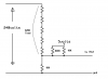
However now i want to design a voltage measurement circuit to measure 240V.
I have no idea what components should i use.
Can anyone suggest any idea where should i go next?
I would like to design a voltage measurement circuit.
What i can understand for now is that i can use the voltage detector IC,BD4850G to measure the voltage which is about 5 V
I'm designing a board to measure the voltage of the electrical appliances plugged to an electrical socket. Then, by measuring the voltage of the electrical appliance, the reading of the voltage will then to be store into the MCU, PIC18F4620.
However now i want to design a voltage measurement circuit to measure 240V.
I have no idea what components should i use.
Can anyone suggest any idea where should i go next?