Continue to Site

Welcome to our site!

Electro Tech is an online community (with over 170,000 members) who enjoy talking about and building electronic circuits, projects and gadgets. To participate you need to register. Registration is free. Click here to register now.

  • Welcome to our site! Electro Tech is an online community (with over 170,000 members) who enjoy talking about and building electronic circuits, projects and gadgets. To participate you need to register. Registration is free. Click here to register now.

Voltage level shifting

Status
Not open for further replies.
Hi Eric,
Both regulators are TS79L00 series, 0.1A fixed. I took a wild guess at providing power for the opamp.. ;o) I've attached an updated circuit diagram. All of the inputs/outputs, level shifting, gain, etc, don't have to be exact as calibration of the sensor will be done in software. The main concern is that the opamp output is within 0V-5V and it's linearity matches as closely as possible to that of the sensor output.

Thanks.
 

Attachments

  • ADC2.jpg
    ADC2.jpg
    85.7 KB · Views: 281
Last edited:
Saiello, your reasoning is sound and your circuit is sound except the -9V regulator needs a minus power supply input, say for example, as from a second 12V battery with its + terminal connected to the - terminal of the first battery. A few comments:

1. I know of no single supply amps that go completely down to zero volts, but at best only within several millivolts of it. So, if you want to go with a single supply amp, be willing to sacrifice some PSI at the lowest end. You don't have that issue with +/- supplies.

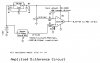
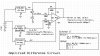
2. Personally, I would go with an amp designed for your purpose, say an AD623 for example. There are many others. It has built-in matched resistors and a single resistor for gain programming. This way you can adjust the gain based on all the extenal components, without matching/changing all four resistors. Some amps even have a built-in precision reference voltage use you can divide to get 1 volts for your offset. Linear Technologies makes amps with built-in references designed as your schematic shows, but with various values of matched resistors inside which can be connected in various combinations to get various gains. Still, with single supply, these do not go done all the way to zero volts. Nonetheless, your circuit should give good results, if not the most precise.

3. Your method of producing the 1V offset should include a capacitor, say 1uf to filter any noise, since noise there will show up on the output amplified by two. With a battery power supply this is less of a concern, but still good practice.

4. The sensor output resistance and the output resistance of the 1 volt source should be matched for best common-mode noise/voltage rejection. Those resistances would be added to each of the 100K input resistors when calculating the gain. With a difference amp you can get the correct gain alright, but I would still make the attempt to match those resistance, or buffer them to produce a nill output resistance. The AD623 has such buffers built-in, thus forming a improved version of the difference amp with three amps, known and an "instrumentation amplifier".

5. I would think that the sensor might need a regulated voltage source to drive it, also. It depends on the sensor. The sensor's output resistance may vary with pressure for all I know, which would pretty much require a buffer amp after it, or the gain of the circuit will change with pressure. A buffer amp may be built-in to the sensor. I don't know.

A lot depends on how much accuracy you want. If you are looking to get pretty well into the ball park than just build what you have in your schematic with a good, precision op amp and 1% resistors.
 
Hi Eric,
Both regulators are TS79L00 series, 0.1A fixed. I took a wild guess at providing power for the opamp.. ;o) I've attached an updated circuit diagram. All of the inputs/outputs, level shifting, gain, etc, don't have to be exact as calibration of the sensor will be done in software. The main concern is that the opamp output is within 0V-5V and it's linearity matches as closely as possible to that of the sensor output.

Thanks.

hi S.
As Curtis explains, you cannot get -V in this way, from a +12V supply.

Looking at the project, all you need is a low cost CA3140 op amp, run it from a single supply of +12V.

The CA3140 output will go down to about 10 to 20mV above 0V [Gnd]

When you consider the full range output of 0V to +5V is required, then you will only lose 0.2% at bottom end!!!..
As its a 10 bit ADC, [~ 4.8mV/bit] thats the bottom 2 bits.

To protect the ADC from voltages greater than +5V, just add a 270R resistor and 5.1V zener as a clamp.

Do you want a circuit using this opa.?
 
Last edited:
hi,
Look at this circuit, it must be a CA3140 opa.:)
 

Attachments

  • Opa2Adc1.gif
    Opa2Adc1.gif
    9.2 KB · Views: 215
Hi eric,
Thanks, that circuit diagram helps me a lot, lots of useful pointers! ;o) I've had my eye on a CA3140 for a while now. One point thought, the ADC is 12 bits, so I'd be losing 4 bits off the bottom, not much I agree but nice to have! ;o) I already have ADC input protection so that's sorted. If I use your circuit but supply the CA3140 with +5V ( convenient supply ) and assume a usable output of 0.5V-4.5V with the ref at 0.5V, will the CA3140 output good linearity over that range?

Many thanks,
Salvatore.

hi,
No, you cannot use a +5V supply, to give a +4.5V output, leave at least a 2V overhead on the supply, so Vsupply would be +7V.
The nearest vreg is a 78L08 100mA at 8V.

The CA3140 opa in one offs is about 50p Stirling.! about 25Cents

IMO its an ideal hobbyist type OPA, also in a dual version CA3240.

For anyone interested the datasheet is attached.
 

Attachments

  • CA3140.pdf
    1.5 MB · Views: 280
I distinctly remember when I saw the CA3140 for the first time when RCA introduced it in the mid-to-late 1970s. I simply could not believe the the vast improvements over the 741-type opamp.

Although better opamps exist today, I fully agree that it is a very useful general purpose opamp, and affordably priced too.
 
Last edited:
Ok, revised circuit attached. Is this finally going to be ok to build? Given generous 0.5V above GND for OPA, caps around Vreg as in datasheet cermet pot for gain adjust to *20..

Thanks,
Salvatore.
 

Attachments

  • ADC3.jpg
    ADC3.jpg
    44.4 KB · Views: 276
Ok, revised circuit attached. Is this finally going to be ok to build? Given generous 0.5V above GND for OPA, caps around Vreg as in datasheet cermet pot for gain adjust to *20..

Thanks,
Salvatore.

hi.

The gain of the inverting input is -G= Rf/Ri, So max gain = ~ 20K/10K =2
[if we ignore the effect of the 1K set pot].

Put a 4K7 resistor in series with the 1K set pot and then decouple the junction with a 1uF cap.

The 0.5V is far to much, 50mV would be more than enough.
 
Last edited:
Status
Not open for further replies.

Latest threads

New Articles From Microcontroller Tips

Back
Top