Continue to Site

Welcome to our site!

Electro Tech is an online community (with over 170,000 members) who enjoy talking about and building electronic circuits, projects and gadgets. To participate you need to register. Registration is free. Click here to register now.

  • Welcome to our site! Electro Tech is an online community (with over 170,000 members) who enjoy talking about and building electronic circuits, projects and gadgets. To participate you need to register. Registration is free. Click here to register now.

Voltage level shifting

Status
Not open for further replies.

saiello

New Member
Hi All,
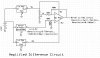
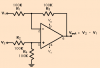
I have a DAQ project on the go, I've built the PC to sensors interface module ( still a few niggles to sort out though but pretty much there ) and am now sourcing a variety of sensors to use with it. The inputs into the DAQ interface ( ADC ) are 0-5V, and I've got my eye on some ( cheap! ) industrial pressure transducers whose outputs are 1-6V. Is there a simple way to linearly shift the 1-6V output of the sensors down to match the 0-5V inputs of the ADC? I know I could use a simple resistive voltage divider circuit but I would only get a 4.167V span and not the full 5V available from the sensor, therefore losing some of the available resolution.

Thanks in advance,
Salvatore.
 
Last edited:
The best way would be a summing amplifier that subtracts 1V from the signal
 
Hi,
Summing amplifier? Could you provide a circuit diagram that would solve my problem?

Thanks.
 
Use the summing amplifier to add -1V to the input signal and invert it
Summing Amplifier
Then invert it again with the inverting amplifier.
Inverting Amplifier
Vcc/Vee should be at least +10V and -10V to give you sufficient headroom
TL082 from Texas Instruments should be a suitable part
 
Last edited:
Thank for the replies! Single supply looks good! So, assuming 12V Vcc, if I apply 1V to the +ve input and 6V to the -ve input, I'd get 5V output? How linear is this output assuming a perfectly linear input of 1-6V on the -ve? The ADC is 12-bit, so 5V/4096=1.22mV per 'division'. Can the output of an op-amp be expected to stay reasonably within 1.22mV linearity from 0-5V, i.e. 0.025%?

Thanks again.

Assuming you are referring to the difference amplifier in the post above, the answer to your first question is yes.

The output resistance of your sensor must be included in the value for R2 (the sensor input side) unless you connect a voltage follower between the sensor and the difference amplifier input. The offset voltage (1 volt) is connected to R1 and the stability of the output of the circuit is directly related to the stability of the offset voltage.

The linearity is determined mainly by the resistors, so the circuit will be adequately linear for low frequency and DC sensor output. The gain of the circuit is low, so the gain will not be affected much by the op amp internal offset voltage, but you should use an op amp with low input bias current (in the nanoamps) since the resistors are large in value. The resistors can be lower (but all equal) if your sensor can work with lower load resistance, thus improving gain accuracy due to input bias. Load resistance is equal to R2. The resistor values should be matched closely or the resulting common mode gain and the differential gain will result in a circuit gain other than Vout=V2-V1.

Your op amp must be the type that can go to zero output voltage (single supply, rail-to-rail, op amp). The op amp must have be unity gain stable (not all are). An op amp with higher CMR gives better gain accurancy if it comes down to a choice of a few op amps you have in mind.
 
Last edited:
Just to make sure we're on the same page, I believe ccurtis is addressing the difference amplifier in this link.To add to ccurtis's excellent response, your op amp input range must extend below 0.5V. Many don't meet that requirement.
The load on the sensor is actually R2+R4, not just R2, although, as ccurtis pointed out, R2 must include the sensor resistance.
V1 must source a maximum of 0.5V/R1, and sink a maximum of 2V/R1. This is not a lot, but it is possible to design a reference that won't do that. Murphy's Law says it will happen if you don't plan for it.:D
 
The load on the sensor is actually R2+R4, not just R2, although, as ccurtis pointed out, R2 must include the sensor resistance.

R2+R4 is the differential input resistance between the two inputs. The input resistance seen by the sensor (the resistance between R2 and ground) is (R2+R4)/2, or R2, since R2 and R4 are equal. The division by 2 is due to the common mode gain being twice the differential gain.
 
1-6V output of the sensors down to match the 0-5V inputs of the ADC?
You need to subtract 1v from the 1 to 6v signal so in principle all you need is a level shifter.
If there were such a thing as a 1v two-terminal precision zener, you connect a resistor to a - supply, then the zener, then a resistor to a + supply.
The 1-6v comes in on the top of the zener, the 0-5v comes out on the bottom of the zener.
No gain change needed.
 
The load on the sensor is actually R2+R4, not just R2, although, as ccurtis pointed out, R2 must include the sensor resistance.

R2+R4 is the differential input resistance between the two inputs. The input resistance seen by the sensor (the resistance between R2 and ground) is (R2+R4)/2, or R2, since R2 and R4 are equal. The division by 2 is due to the common mode gain being twice the differential gain.
Just in case we are talking about different schematics, I have attached the one I'm talking about below.
The sensor connects between V2 and ground. The load on V2 is R2+R4. V1 has no effect on the resistance seen by V2. The op amp has no effect on the resistance seen by V2. Feedback has no effect on the resistance seen by V2.
Differential resistance in this case is irrelevant, since V2 is a sensor input, and V1 is a reference input.
 

Attachments

  • differential amp.png
    differential amp.png
    3.2 KB · Views: 270
You need to subtract 1v from the 1 to 6v signal so in principle all you need is a level shifter.
If there were such a thing as a 1v two-terminal precision zener, you connect a resistor to a - supply, then the zener, then a resistor to a + supply.
The 1-6v comes in on the top of the zener, the 0-5v comes out on the bottom of the zener.
No gain change needed.
A level shifter is what we're talking about. We're addressing a practical way to do it.:)
 
Roff, thanks for setting me straight. We are indeed talking about the same schematic. I have to tell you, though, I am looking straight at an op amp circuit design textbook of mine that gives the single ended input resistance (at either input) as the average of the two input resistors, in black and white! Of course, just looking at the circuit there is next to zero base current and the input resistor and the grounded resistor are in series for a total of R2+R4. Thanks for correcting my gross error. No BS.
 
Roff, thanks for setting me straight. We are indeed talking about the same schematic. I have to tell you, though, I am looking straight at an op amp circuit design textbook of mine that gives the single ended input resistance (at either input) as the average of the two input resistors, in black and white! Of course, just looking at the circuit there is next to zero base current and the input resistor and the grounded resistor are in series for a total of R2+R4. Thanks for correcting my gross error. No BS.
No problem. I wish I could see your textbook.:)
 
No problem. I wish I could see your textbook.:)

Sure thing. In file diffamp2, under "design parameters", see that Rinc is defined as common mode input resistance, between either input and ground. In file diffamp3, under "design equations", design equation 6, see that Rinc equals the average of the input resistors.

Now if it had defined Rinc as the input resistance of both inputs tied together and ground, it might make sense, but that is not how it is worded. Even then, it would be the two resistors in parallel, not the average of them.
 

Attachments

  • diffamp.JPG
    diffamp.JPG
    515.1 KB · Views: 186
  • diffamp2.JPG
    diffamp2.JPG
    854.9 KB · Views: 206
  • diffamp3.JPG
    diffamp3.JPG
    787.7 KB · Views: 194
Last edited:
Thanks for the replies, although I have to say most went way over my head..! ;o) As far as I can gather there are two major problems to overcome first, the input and output levels. Given the single ended supply, the op amp may have trouble with 0.5V inputs and could certainly have trouble with outputting 0V ( when V1=V2 ). Having looked again at my requirements, a change of plan might better suit me and possibly solve at least the opamp input problem. To explain: The pressure sensor has a range of 0-870psi over a 1V-6V range. I would only be interested in reading a maximum of 400psi. It would be better for me if I were to take the lower end of the signal range of the sensor, say 1V-3.5V ( equating to 0-435psi ), shift the level down 1V and 'stretch' the now 0V-2.5V output to a 0V-5V span. This would effectively double the sensitivity of the sensor in the range I would be interested in. This diagram seems to fit the bill. If I set R1=100K and R3 to 200K, I should in theory get the required output. With V1=V2=1V the voltages at pins 2 and 3 would be 0.67V so hopefully overcoming the input problem.Having said that, with the opamp being single supply, the second major problem still remains, i.e. an output of 0V. Are there examples of opamps that will cope with this? My understanding is that it was only comparators were able to perform this trick? In addition to the above can I simply use a resistive voltage divider to generate V1 or will this upset the calculations involving R1 and R3? If not, how would you go about supplying a 1V reference? To recap on all of the above, is it really possible to find a solution to my problem with a single-ended supply opamp or would I need to look at a dual supply solution? I've attached a diagram with this in mind. This would also be useful as a general scheme if I wanted to further decrease the range and increase the sensitivity of the sensor by adjusting R1 and R3 accordingly. Please feel free to rip it apart ( in novice terms please! ) ;o)

Thanks again.
 

Attachments

  • ADC.jpg
    ADC.jpg
    78.8 KB · Views: 208
hi. S.

What type of regulator is that -9V on the diagram.?
 
Sure thing. In file diffamp2, under "design parameters", see that Rinc is defined as common mode input resistance, between either input and ground. In file diffamp3, under "design equations", design equation 6, see that Rinc equals the average of the input resistors.

Now if it had defined Rinc as the input resistance of both inputs tied together and ground, it might make sense, but that is not how it is worded. Even then, it would be the two resistors in parallel, not the average of them.
There are several weird things about that text:
1. They define Vic as the input offset voltage of the amplifier. In their schematic, it's the input common mode voltage.
2. At the top of p9-2, they equate Vic to the average of v1 and v2. If Vic were replaced by a short circuit in the schematic, then the common mode voltage could be defined as the average of v1 and v2, but Vic is shown as a separate source.
3. They say on p9-4 that the common mode input resistance Rinc=(R1+R2)/2. By my definition of common-mode input resistance (Rinc=Vic/Iic), Rinc=(R1+R3)||(R2+R4). This gives a different answer than does their equation.

I agree that the differential input resistance is R1+R2. They didn't address the individual input resistances for v1 and v2.
 
I'm with you there, Ron. They can define things whatever way, but as a practical matter the input resistance is E/I at the input.
 
Status
Not open for further replies.

Latest threads

New Articles From Microcontroller Tips

Back
Top