Continue to Site

Welcome to our site!

Electro Tech is an online community (with over 170,000 members) who enjoy talking about and building electronic circuits, projects and gadgets. To participate you need to register. Registration is free. Click here to register now.

  • Welcome to our site! Electro Tech is an online community (with over 170,000 members) who enjoy talking about and building electronic circuits, projects and gadgets. To participate you need to register. Registration is free. Click here to register now.

Voltage Drop

Status
Not open for further replies.

Micheal

New Member
Hi All,

I'm a new learner in Electronic and the attached is my exercise question which required your help.

Please find the voltage drop across the 1 Ohm resistor.

Thanks in advance.

Regards,
Micheal
 

Attachments

  • untitled.JPG
    untitled.JPG
    6.2 KB · Views: 586
All the resistors are connected in parallel.

Work out the total resistance using the resistors in parallel formula.

Calculate the voltage across all the resistors using Ohm's law.

Hint: one of the resistors is short circuit and will have no voltage across it and therefor no current flow.
 
Hint: one of the resistors is short circuit and will have no voltage across it
Correct.

and therefor no current flow.
Mmm... I dont think so.

Current flows quite nicely in a short circuit (a piece of wire).

I think you intended to say, "and therefore no current will flow in a resistor connected in parallel".

JimB
 
Hi Hero999,

Did you mean that the right bottom 2 ohm is parallel to 1 ohm and parallel to 3 ohms?

I'm not clear with this circuit layout?

Please advice,

Thanks
 
Hi All,

I'm a new learner in Electronic and the attached is my exercise question which required your help.

Please find the voltage drop across the 1 Ohm resistor.

Thanks in advance.

Regards,
Micheal

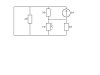
Combine the 2 and 1 Ohm resistors into an equivalent resistance. Redraw the circuit noting that a wire that shorts across a resistor eliminates it from consideration. You will find the current source has two separate resistances across it. Combine them for an equiv resistance and then calculate the voltage caused by 2A of current.

If you don't get it by tomorrow, I'll post the answer.
 
Last edited:
Last edited:
i agree with you, all resistors are in parallel
all you have to do is to resolve to resistors from left to right
i think that will help you get total the voltage
find your way from there:confused:
 
Hi All,

Found out that the left side resistor, there is an extra wire - is that what you mean short circuit?

By the way, I try to solve it from right to left - headache.

Please advice again,
Thanks
 
Hi All,

Found out that the left side resistor, there is an extra wire - is that what you mean short circuit?
That's what we've being trying to tell you.

By the way, I try to solve it from right to left - headache.
Did you read the replies?

For the final time, the resistors are in parallel, see Wikipedia for working out the total resistance then calculate the voltage using Ohm's law.
Resistor - Wikipedia, the free encyclopedia
 
Last edited:
Hi All,

My answer for the voltage drop at 1 ohm is 1.89V.

Please check whether correct or not?

Thanks again.
 
No, that's wrong.

Hint: each resistor has the same voltage across it.
 
Hi All,

I'm a new learner in Electronic and the attached is my exercise question which required your help.

Please find the voltage drop across the 1 Ohm resistor.

Thanks in advance.

Regards,
Micheal
Try this: designate the long wire that wraps around the outside of the schematic as ground and then redraw the schematic. One side of the current source connects to the ground line, one side of every resistor connects to ground. I believe you will see how the current source is connected across all the resistors in parallel. You will also notice one of the resistors is connected to two different points of the ground line, so it has no current through it and can be eliminated.
 
Last edited:
Hi bountyhunter,

What I found out that the left most resistor will become zero current source as the short circuit. For the top right most it will become 6 V, right?

How about the right most bottom 1 & 2 Ohms?

I really get stucked here.

Please help out.

Thanks
 
Hi All,

Please show the circuitry in the simple way. What I get stucked is the current source location and the top & Bottom loop separated with a single wire, what will affect the total current?

Please advice.

Thanks
Micheal
 
I've redrawn it for you.

Note that the signs across the resistor are opposite to the supply so the voltage will b negative. Don't allow this to confuse you, just put a - sign in front of your answer.:D
 

Attachments

  • Rproblem1.GIF
    Rproblem1.GIF
    2.2 KB · Views: 149
What happened to the 1 Ohm parallel the lower right hand 2 Ohm?
there is a series/parallel combo of 2 + (1//2) = 2 + (2/3) = 2.6666 Ohm, that should parallel your 3 Ohm and the source?
 
Hi Hero999,

The sign is reverse as what you mentioned. But I see the direction of the current across the V3 should be on top + sign.

Please advice why?

Thanks again
 
What happened to the 1 Ohm parallel the lower right hand 2 Ohm?
there is a series/parallel combo of 2 + (1//2) = 2 + (2/3) = 2.6666 Ohm, that should parallel your 3 Ohm and the source?
It has a wire across it so it effectively disappears.

Hi Hero999,

The sign is reverse as what you mentioned.
No it's not, the sign on my circuit is the same as the original: the + goes to the - side of the power supply.


But I see the direction of the current across the V3 should be on top + sign.

Please advice why?

Thanks again
What happens if you connect a DVM up with the - input to the positive supply and the + input to the negative supply? It displays a negative voltage.

The signs on the circuit have been put this way to make you think.
 
2) Add series of left hand 2 Ohm and combo 2/3 Ohm (1 parallel 2) = 2.666 Ohm
You're not listening, the left hand 2Ω resistor has a piece of wire across it so its resistance is 0Ω.

The voltage across the 2Ω resistor will be 0V.

Look at my previous attachment.

so V(1) = (-) 0.706Volts
That's wrong.

The resistances are all in parallel, I'm not going to say this again.
 
Last edited:
Status
Not open for further replies.

Latest threads

New Articles From Microcontroller Tips

Back
Top